Lexus RX (RX 350L, RX450h) 2016-2025 Repair Manual: Removal
REMOVAL
CAUTION / NOTICE / HINT
The necessary procedures (adjustment, calibration, initialization, or registration) that must be performed after parts are removed and installed, or replaced during front axle hub sub-assembly removal/installation are shown below.
Necessary Procedures After Parts Removed/Installed/Replaced| Replaced Part or Performed Procedure | Necessary Procedure | Effect/Inoperative Function when Necessary Procedure not Performed | Link |
|---|---|---|---|
| Front wheel alignment adjustment | Calibration |
| |
HINT:
- Use the same procedure for the RH side and LH side.
- The following procedure is for the LH side.
PROCEDURE
1. REMOVE FRONT WHEEL
Click here .gif)
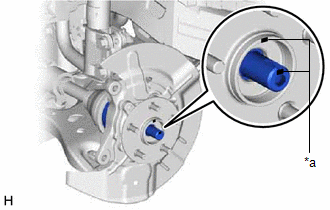
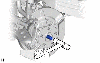
2. REMOVE FRONT AXLE SHAFT NUT
Click here
3. SEPARATE FRONT SPEED SENSOR (w/o AVS)
| (a) Disengage the 2 claws and separate the sensor clamp. |
|
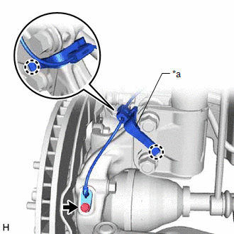
(b) Remove the bolt and separate the front speed sensor from the steering knuckle.
NOTICE:
- Prevent foreign matter from contacting the sensor tip.
- Be careful not to damage the front speed sensor.
- Clean the speed sensor installation hole and the contact surfaces every time the speed sensor is removed.
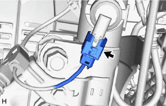
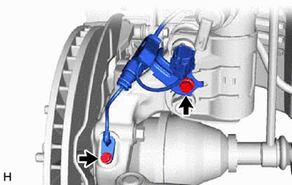
4. SEPARATE FRONT SPEED SENSOR (w/ AVS)
| (a) Disconnect the AVS connector from the absorber control actuator. |
|
| (b) Remove the 2 bolts and separate the front speed sensor from the front shock absorber assembly and steering knuckle. NOTICE:
|
|
5. SEPARATE TIE ROD ASSEMBLY
Click here
6. SEPARATE FRONT DISC BRAKE CALIPER ASSEMBLY
Click here
7. REMOVE FRONT DISC
Click here
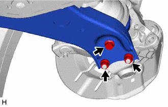
8. SEPARATE FRONT LOWER NO. 1 SUSPENSION ARM SUB-ASSEMBLY
| (a) Remove the bolt, 2 nuts and separate the front lower No. 1 suspension arm sub-assembly from the front lower ball joint assembly. |
|
9. SEPARATE FRONT DRIVE SHAFT ASSEMBLY
| (a) Put matchmarks on the front drive shaft assembly and the front axle hub sub-assembly. |
|
| (b) Using a plastic hammer, separate the front drive shaft assembly from the front axle assembly. NOTICE:
HINT: If it is difficult to separate the front drive shaft assembly from the front axle assembly, tap the end of the front drive shaft assembly using a brass bar and a hammer. |
|
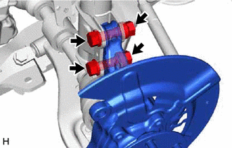
10. REMOVE FRONT AXLE ASSEMBLY
| (a) Remove the 2 bolts, 2 nuts and front axle assembly from the front shock absorber assembly. NOTICE: When removing the nuts, keep the bolts from rotating. |
|
11. REMOVE FRONT AXLE HUB SUB-ASSEMBLY
| (a) Secure the front axle assembly between aluminum plates in a vise. NOTICE: Do not overtighten the vise. |
|
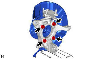
(b) Remove the 4 bolts, front axle hub sub-assembly and front disc brake dust cover from the steering knuckle.
NOTICE:
- Do not drop the front axle hub sub-assembly.
- Be careful not to damage the speed sensor rotor or contact surfaces.
- Do not allow foreign matter to contact the speed sensor rotor or contact surfaces.
 On-vehicle Inspection
ON-VEHICLE INSPECTION CAUTION / NOTICE / HINT HINT:
Use the same procedure for the RH side and LH side.
The following procedure is for the LH side.
PROCEDURE 1. REMOVE FRONT WHEEL Click here ...
 Installation
INSTALLATION CAUTION / NOTICE / HINT HINT:
Use the same procedure for the RH side and LH side.
The following procedure is for the LH side.
PROCEDURE 1. INSTALL FRONT AXLE HUB SUB-ASSEMBLY (a) ...
Other materials:
Lexus RX (RX 350L, RX450h) 2016-2025 Repair Manual > Intuitive Parking Assist System (w/ Intelligent Clearance Sonar System): Diagnosis System
DIAGNOSIS SYSTEM DESCRIPTION (a) When troubleshooting a vehicle with a diagnosis system, the only difference from the usual troubleshooting procedure is connecting the Techstream to the vehicle and reading various data output from the clearance warning ECU assembly. The clearance warning ECU assembl ...
Lexus RX (RX 350L, RX450h) 2016-2025 Repair Manual > Trip Switch: Components
COMPONENTS ILLUSTRATION *1 COWL SIDE TRIM BOARD LH *2 FRONT DOOR SCUFF PLATE LH *3 HOOD LOCK CONTROL LEVER SUB-ASSEMBLY *4 INSTRUMENT CLUSTER FINISH PANEL ORNAMENT *5 INSTRUMENT CLUSTER FINISH PANEL SUB-ASSEMBLY *6 INSTRUMENT PANEL GARNISH LH *7 LOWER INSTRUMENT F ...
Lexus RX (RX 350L, RX450h) 2016-{YEAR} Owners Manual
- For your information
- Pictorial index
- For safety and security
- Instrument cluster
- Operation of each component
- Driving
- Lexus Display Audio system
- Interior features
- Maintenance and care
- When trouble arises
- Vehicle specifications
- For owners
Lexus RX (RX 350L, RX450h) 2016-{YEAR} Repair Manual

0.0141