Lexus RX (RX 350L, RX450h) 2016-2025 Repair Manual: Inspection
INSPECTION
PROCEDURE
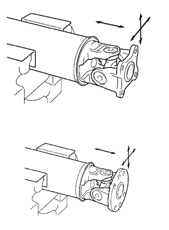
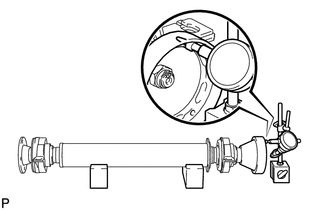
1. INSPECT SPIDER BEARING
| (a) Check that the spider bearing rotates smoothly. |
|
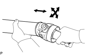
| (b) Check that there is no play in the spider bearing. If necessary, replace the propeller with center bearing shaft assembly. |
|
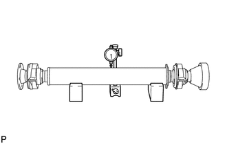
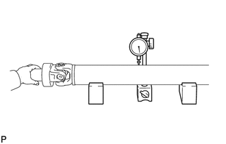
2. INSPECT INTERMEDIATE SHAFT ASSEMBLY
| (a) Using a dial indicator, measure the runout of the intermediate shaft assembly. Maximum Runout: 0.4 mm (0.0157 in.) NOTICE: The dial indicator must be set at a right angle to the center of the intermediate shaft assembly. If the shaft runout exceeds the maximum, replace the propeller with center bearing shaft assembly. |
|
| (b) Using a dial indicator, measure the runout of the universal joint flange (for front side). Maximum Runout: 0.1 mm (0.00394 in.) If the shaft runout exceeds the maximum, replace the propeller with center bearing shaft assembly. |
|
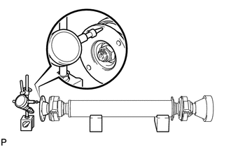
| (c) Using a dial indicator, measure the runout of the universal joint flange (for rear side). Maximum Runout: 0.1 mm (0.00394 in.) If the shaft runout exceeds the maximum, replace the propeller with center bearing shaft assembly. |
|
| (d) Using a dial indicator, measure the runout of the universal joint flange (for rear side). Maximum Runout: 0.1 mm (0.00394 in.) If the shaft runout exceeds the maximum, replace the propeller with center bearing shaft assembly. |
|
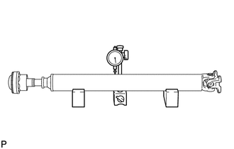
3. INSPECT PROPELLER SHAFT ASSEMBLY
| (a) Using a dial indicator, measure the runout of the propeller shaft assembly. Maximum Runout: 0.4 mm (0.0157 in.) NOTICE: The dial indicator must be set at a right angle to the center of the propeller shaft assembly. If the shaft runout exceeds the maximum, replace the propeller with center bearing shaft assembly. |
|
4. INSPECT REAR PROPELLER SHAFT ASSEMBLY
| (a) Using a dial indicator, measure the runout of the rear propeller shaft assembly. Maximum Runout: 0.4 mm (0.0157 in.) NOTICE: The dial indicator must be set at a right angle to the center of the rear propeller shaft assembly. If the shaft runout exceeds the maximum, replace the propeller with center bearing shaft assembly. |
|
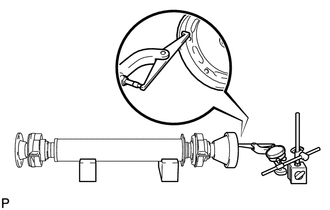
5. INSPECT CENTER NO. 2 SUPPORT BEARING ASSEMBLY
| (a) Turn the center No. 2 support bearing assembly by hand. |
|
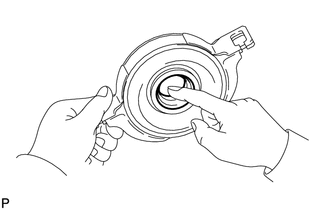
(b) Check that the center No. 2 support bearing assembly turns smoothly, and check that the seals are not cracked or damaged.
If the center No. 2 support bearing assembly is damaged or worn, or does not turn smoothly, replace it.
 Removal
REMOVAL PROCEDURE 1. REMOVE NO. 2 ENGINE UNDER COVER Click here 2. REMOVE FRONT FLOOR COVER LH Click here 3. REMOVE FRONT CENTER FLOOR COVER for TMC Made: Click here for TMMC Made: Click he ...
 Installation
INSTALLATION PROCEDURE 1. TEMPORARILY TIGHTEN PROPELLER WITH CENTER BEARING SHAFT ASSEMBLY (a) Remove SST from the transfer assembly. (b) Insert the propeller with center bearing shaft ...
Other materials:
Lexus RX (RX 350L, RX450h) 2016-2025 Repair Manual > Air Cooled Oil Cooler: Removal
REMOVAL CAUTION / NOTICE / HINT The necessary procedures (adjustment, calibration, initialization, or registration) that must be performed after parts are removed and installed, or replaced during oil cooler assembly removal/installation are shown below. Necessary Procedure After Parts Removed/Insta ...
Lexus RX (RX 350L, RX450h) 2016-2025 Repair Manual > Front Camera System: Steering Vibrator System Missing Message (C1A7587)
DESCRIPTION The forward recognition camera communicates with the steering vibration ECU via LIN communication. If a communication error between the forward recognition camera and steering vibration ECU is detected, DTC C1A7587 is stored. DTC No. Detection Item DTC Detection Condition Troubl ...
Lexus RX (RX 350L, RX450h) 2016-{YEAR} Owners Manual
- For your information
- Pictorial index
- For safety and security
- Instrument cluster
- Operation of each component
- Driving
- Lexus Display Audio system
- Interior features
- Maintenance and care
- When trouble arises
- Vehicle specifications
- For owners
Lexus RX (RX 350L, RX450h) 2016-{YEAR} Repair Manual

0.0135