Lexus RX (RX 350L, RX450h) 2016-2025 Repair Manual: Removal
REMOVAL
CAUTION / NOTICE / HINT
The necessary procedures (adjustment, calibration, initialization or registration) that must be performed after parts are removed and installed, or replaced during camshaft position sensor removal/installation are shown below.
Necessary Procedures After Parts Removed/Installed/Replaced| Replaced Part or Performed Procedure | Necessary Procedure | Effect/Inoperative Function when Necessary Procedure not Performed | Link |
|---|---|---|---|
| Battery terminal is disconnected/reconnected | Memorize steering angle neutral point | Lane Control System | |
| Pre-collision System | |||
| Intelligent Clearance Sonar System*1 | |||
| Parking Assist Monitor System | | ||
| Panoramic View Monitor System | | ||
| Lighting System (w/ Automatic Headlight Beam Level Control System) | | ||
| Initialize back door lock | Power Door Lock Control System | | |
| Reset back door close position | Power Back Door System (w/ Outside Door Control Switch) | | |
| Inspection After Repair |
| |
*1: When performing learning using the Techstream.
Click here .gif)
PROCEDURE
1. REMOVE INTAKE AIR SURGE TANK ASSEMBLY
Click here
2. REMOVE VVT SENSOR (for Intake Side of Bank 1)
| (a) Disconnect the VVT sensor connector. |
|
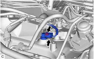
(b) Remove the bolt and VVT sensor from the cylinder head cover sub-assembly.
NOTICE:
If the VVT sensor has been struck or dropped, replace it.
3. REMOVE VVT SENSOR (for Exhaust Side of Bank 1)
| (a) Disconnect the VVT sensor connector. |
|
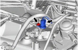
(b) Remove the bolt and VVT sensor from the cylinder head cover sub-assembly.
NOTICE:
If the VVT sensor has been struck or dropped, replace it.
4. REMOVE VVT SENSOR (for Intake Side of Bank 2)
| (a) Disconnect the VVT sensor connector. |
|
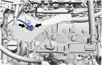
(b) Remove the bolt and VVT sensor from the cylinder head cover sub-assembly LH.
NOTICE:
If the VVT sensor has been struck or dropped, replace it.
5. REMOVE VVT SENSOR (for Exhaust Side of Bank 2)
| (a) Disconnect the VVT sensor connector. |
|
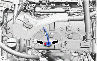
(b) Remove the bolt and VVT sensor from the cylinder head cover sub-assembly LH.
NOTICE:
If the VVT sensor has been struck or dropped, replace it.
 Components
COMPONENTS ILLUSTRATION *1 VVT SENSOR (for Intake Side of Bank 1) *2 VVT SENSOR (for Exhaust Side of Bank 1) *3 VVT SENSOR (for Intake Side of Bank 2) *4 VVT SENSOR (for Exhaust Si ...
 Installation
INSTALLATION PROCEDURE 1. INSTALL VVT SENSOR (for Exhaust Side of Bank 2) (a) Apply a light coat of engine oil to the O-ring of the VVT sensor. NOTICE: If reusing the VVT sensor, be sure to inspect th ...
Other materials:
Lexus RX (RX 350L, RX450h) 2016-2025 Repair Manual > Can Communication System: Restraints Occupant Classification System Module Communication Stop Mode
DESCRIPTION Detection Item Symptom Trouble Area Restraints Occupant Classification System Module Communication Stop Mode Either condition is met:
"Occupant Detection" is not displayed on the CAN Bus Check screen of the Techstream.
Click here
Communication system DTCs (DTCs tha ...
Lexus RX (RX 350L, RX450h) 2016-2025 Repair Manual > Fuel Pump (for Tmmc Made): Disassembly
DISASSEMBLY CAUTION / NOTICE / HINT NOTICE:
Do not disconnect the tube shown in the illustration when disassembling the fuel suction tube with pump and gauge assembly. Doing so will cause reassembly of the fuel suction tube with pump and gauge assembly to be impossible as the tube is pressed into ...
Lexus RX (RX 350L, RX450h) 2016-{YEAR} Owners Manual
- For your information
- Pictorial index
- For safety and security
- Instrument cluster
- Operation of each component
- Driving
- Lexus Display Audio system
- Interior features
- Maintenance and care
- When trouble arises
- Vehicle specifications
- For owners
Lexus RX (RX 350L, RX450h) 2016-{YEAR} Repair Manual

0.0133