Lexus RX (RX 350L, RX450h) 2016-2025 Repair Manual: Drive Start Control
DESCRIPTION
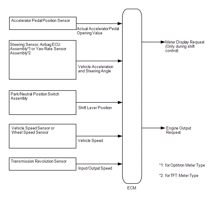
The drive start control is controlled by the ECM.
If the ECM determines that the shift lever and accelerator pedal are operated abnormally, engine output is restricted and, when necessary, a warning is displayed on the combination meter assembly.
CAUTION / NOTICE / HINT
HINT:
Even if the accelerator pedal position is maintained, the engine output may increase when driving uphill and decrease when driving downhill. This is due to the drive start control controlling the engine output, and is not a malfunction.
PROCEDURE
| 1. | SYMPTOM CONFIRMATION |
(a) Interview the customer to confirm the problem.
| Result | Proceed to |
|---|---|
| Hunting | A |
| Hesitation/poor acceleration | B |
| B | .gif) | GO TO STEP 8 |
|
.gif)
| 2. | PAST ACTIVATION CONFIRMATION |
(a) Check if the customer operated the vehicle in a way that would cause the drive start control to operate.
Drive Start Control Activation ConditionsHINT:
Condition 1 (Reverse control)
Activation conditions
- The shift lever is in R.
-
The accelerator pedal is depressed excessively.
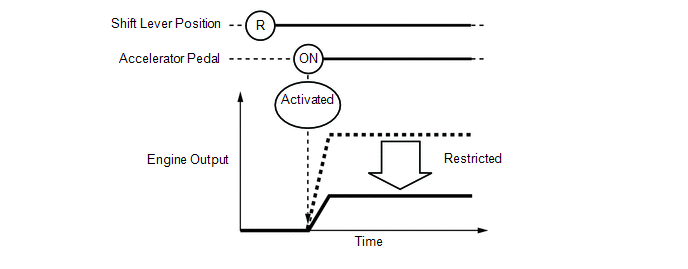
Items Controlled
- Engine output is restricted.
Deactivation Conditions
- The shift lever is moved to any position other than R.
- The accelerator pedal is released.
Condition 2 (Shift control a)
Activation conditions
- The shift lever is moved from P to any forward position (D, S or M) or R.
-
The accelerator pedal is open by approximately 1/5 or more.
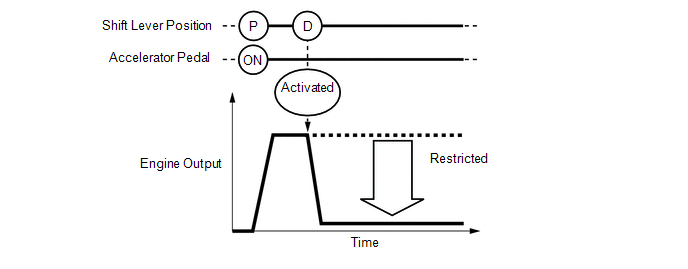
Items Controlled
- Engine output is restricted.
Deactivation Conditions
- The shift lever is in P or N.
- The accelerator pedal is released.
Condition 3 (Shift control b)
Activation conditions
- The shift lever is moved from R to any forward position (D, S or M), any forward position (D, S or M) to R, or N to R.
-
The accelerator pedal is open by approximately 1/5 or more.
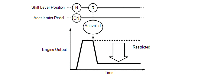
Items Controlled
- Engine output is restricted.
Deactivation Conditions
- The shift lever is in P or N.
- The accelerator pedal is released.
HINT:
During reverse control or shift control, engine output is adjusted based on the road gradient and steering angle.
| Result | Proceed to |
|---|---|
| Performed | A |
| Not performed | B |
| B | | SYSTEM NORMAL (GO TO PROBLEM SYMPTOM TABLE) |
|
| 3. | CHECK DTC OUTPUT |
(a) Connect the Techstream to the DLC3.
(b) Turn the engine switch on (IG).
(c) Turn the Techstream on.
(d) Enter the following menus: System Select / Health Check.
(e) Check the DTCs.
| Result | Proceed to |
|---|---|
| DTCs are not output | A |
| DTCs are output | B |
| B | | GO TO DTC CHART |
|
| 4. | READ VALUE USING TECHSTREAM (FR, FL, RR, RL WHEEL SPEED) |
(a) Connect the Techstream to the DLC3.
(b) Turn the engine switch on (IG).
(c) Turn the Techstream on.
(d) Start the engine.
(e) Enter the following menus: Chassis / Brake/EPB / Data List / FR Wheel Speed, FL Wheel Speed, RR Wheel Speed and RL Wheel Speed.
Chassis > Brake/EPB > Data List| Tester Display |
|---|
| FR Wheel Speed |
| FL Wheel Speed |
| RR Wheel Speed |
| RL Wheel Speed |
(f) Read the value displayed on the Techstream.
Standard:
| Techstream Display | Condition | Specified Condition |
|---|---|---|
| FR Wheel Speed FL Wheel Speed RR Wheel Speed RL Wheel Speed | Vehicle stopped, engine running | 0 km/h (0 mph) |
| Vehicle being driven at constant speed between 16.1 to 64.4 km/h (10 to 40 mph) | No large fluctuations when driving at a constant speed |
CAUTION:
When performing a drive test, obey all speed limits and traffic laws.
HINT:
Data can be captured relatively easily by using the snapshot function in the Data List. Confirm the data after performing the drive test.
| NG | | INSPECT FRONT OR REAR SPEED SENSOR |
|
| 5. | READ VALUE USING TECHSTREAM (OUTPUT AXIS SPEED) |
(a) Connect the Techstream to the DLC3.
(b) Turn the engine switch on (IG).
(c) Turn the Techstream on.
(d) Start the engine.
(e) Enter the following menus: Powertrain / Engine / Data List / Output Axis Speed.
Powertrain > Engine > Data List| Tester Display |
|---|
| Output Axis Speed |
(f) Read the value displayed on the Techstream.
Standard:
| Techstream Display | Condition | Specified Condition |
|---|---|---|
| Output Axis Speed | Vehicle stopped, engine running | 0 rpm |
| Vehicle being driven at a constant speed of approximately 60 km/h (37 mph) | No large fluctuations when driving at a constant speed |
CAUTION:
When performing a drive test, obey all speed limits and traffic laws.
HINT:
Data can be captured relatively easily by using the snapshot function in the Data List. Confirm the data after performing the drive test.
| NG | | INSPECT TRANSMISSION REVOLUTION SENSOR |
|
| 6. | READ VALUE USING TECHSTREAM (LATERAL G AND FORWARD AND REARWARD G) |
(a) Connect the Techstream to the DLC3.
(b) Turn the engine switch on (IG).
(c) Turn the Techstream on.
(d) Start the engine.
(e) Enter the following menus: Chassis / Brake/EPB / Data List / Lateral G and Forward and Rearward G.
Chassis > Brake/EPB > Data List| Tester Display |
|---|
| Lateral G |
| Forward and Rearward G |
(f) Read the value displayed on the Techstream.
Standard:
| Techstream Display | Condition | Specified Condition |
|---|---|---|
| Lateral G Forward and Rearward G | During deceleration | Value changes with vehicle speed |
| During acceleration | Value changes with vehicle speed |
CAUTION:
When performing a drive test, obey all speed limits and traffic laws.
HINT:
Data can be captured relatively easily by using the snapshot function in the Data List. Confirm the data after performing the drive test.
| Result | Proceed to |
|---|---|
| OK | A |
| NG (for Optitron Meter Type) | B |
| NG (for TFT Meter Type) | C |
| B | | INSPECT AIRBAG SENSOR ASSEMBLY |
| C | | INSPECT YAW RATE SENSOR ASSEMBLY |
|
| 7. | READ VALUE USING TECHSTREAM (STEERING ANGLE VALUE) |
(a) Connect the Techstream to the DLC3.
(b) Turn the engine switch on (IG).
(c) Turn the Techstream on.
(d) Start the engine.
(e) Enter the following menus: Chassis / Brake/EPB / Data List / Steering Angle Value.
Chassis > Brake/EPB > Data List| Tester Display |
|---|
| Steering Angle Value |
(f) Read the value displayed on the Techstream.
Standard:
| Techstream Display | Condition | Specified Condition |
|---|---|---|
| Steering Angle Value | Steering wheel turned left | Value increases with steering wheel operation |
| Steering wheel turned right | Value decreases with steering wheel operation |
CAUTION:
When performing a drive test, obey all speed limits and traffic laws.
HINT:
Data can be captured relatively easily by using the snapshot function in the Data List. Confirm the data after performing the drive test.
| OK | | SYSTEM NORMAL (GO TO PROBLEM SYMPTOM TABLE) |
| NG | | INSPECT STEERING SENSOR |
| 8. | PAST ACTIVATION CONFIRMATION |
(a) Check if the customer operated the vehicle in a way that would cause the drive start control to operate.
Drive Start Control Activation ConditionsHINT:
Condition 1 (Reverse control)
Activation conditions
- The shift lever is in R.
-
The accelerator pedal is depressed excessively.
Items Controlled
- Engine output is restricted.
Deactivation Conditions
- The shift lever is moved to any position other than R.
- The accelerator pedal is released.
Condition 2 (Shift control a)
Activation conditions
- The shift lever is moved from P to any forward position (D, S or M) or R.
-
The accelerator pedal is open by approximately 1/5 or more.
Items Controlled
- Engine output is restricted.
Deactivation Conditions
- The shift lever is in P or N.
- The accelerator pedal is released.
Condition 3 (Shift control b)
Activation conditions
- The shift lever is moved from R to any forward position (D, S or M), any forward position (D, S or M) to R, or N to R.
-
The accelerator pedal is open by approximately 1/5 or more.
Items Controlled
- Engine output is restricted.
Deactivation Conditions
- The shift lever is in P or N.
- The accelerator pedal is released.
HINT:
During reverse control or shift control, engine output is adjusted based on the road gradient and steering angle.
| Result | Proceed to |
|---|---|
| Not performed | A |
| Performed | B |
HINT:
If the customer operated the vehicle in a way which caused the drive start control to operate, explain the operation of the system to the customer and that the operation is not a malfunction.
| B | | SYSTEM NORMAL |
|
| 9. | CHECK DTC OUTPUT |
(a) Connect the Techstream to the DLC3.
(b) Turn the engine switch on (IG).
(c) Turn the Techstream on.
(d) Enter the following menus: System Select / Health Check.
(e) Check the DTCs.
| Result | Proceed to |
|---|---|
| DTCs are not output | A |
| DTCs are output | B |
| B | | GO TO DTC CHART |
|
| 10. | INSPECT PARK/NEUTRAL POSITION SWITCH ASSEMBLY |
(a) Inspect the park/neutral position switch assembly.
-
for 2WD models: Click here
.gif)
-
for AWD models: Click here
| Result | Proceed to |
|---|---|
| Normal | A |
| Abnormal | B |
| B | | REPLACE PARK/NEUTRAL POSITION SWITCH ASSEMBLY |
|
| 11. | READ VALUE USING TECHSTREAM (ACCELERATOR PEDAL POSITION SENSOR) |
(a) Connect the Techstream to the DLC3.
(b) Turn the engine switch on (IG).
(c) Turn the Techstream on.
(d) Enter the following menus: Powertrain / Engine / Data List / Accelerator Position Sensor No.1 Voltage % and Accelerator Position Sensor No.2 Voltage %.
Powertrain > Engine > Data List| Tester Display |
|---|
| Accelerator Position Sensor No.1 Voltage % |
| Accelerator Position Sensor No.2 Voltage % |
(e) Read the value displayed on the Techstream.
OK:
| Techstream Display | Condition | Specified Condition |
|---|---|---|
| Accelerator Position Sensor No.1 Voltage % | Accelerator Pedal Released → Depressed | Values smoothly change following accelerator pedal operation |
| Accelerator Position Sensor No.2 Voltage % |
HINT:
For numerical values of Accelerator Position Sensor No.1 Voltage % and Accelerator Position Sensor No.2 Voltage %, refer to the Data List.
Click here
| OK | | SYSTEM NORMAL (GO TO PROBLEM SYMPTOM TABLE) |
| NG | | REPLACE ACCELERATOR PEDAL(W/SENSOR) ROD ASSEMBLY |
 Ignition Circuit
DESCRIPTION A direct ignition system is used on this vehicle. The direct ignition system is a 1 cylinder ignition system which ignites one cylinder with one ignition coil. In the 1 cylinder ignition s ...
 Rough Idling
DESCRIPTION Problem Symptom Suspected Area Trouble Area
Engine speed fluctuation due to abnormal combustion
Idle speed too low or high
Strong engine vibration due to above symptoms ...
Other materials:
Lexus RX (RX 350L, RX450h) 2016-2025 Repair Manual > Vacuum Warning Switch: Components
COMPONENTS ILLUSTRATION *1 OUTER COWL TOP PANEL SUB-ASSEMBLY - - N*m (kgf*cm, ft.*lbf): Specified torque - - ILLUSTRATION *A for TMC Made - - *1 CHECK VALVE GROMMET *2 VACUUM WARNING SWITCH ASSEMBLY ● Non-reusable part - - ILLUSTRATION * ...
Lexus RX (RX 350L, RX450h) 2016-2025 Repair Manual > Ecm: Removal
REMOVAL CAUTION / NOTICE / HINT The necessary procedures (adjustment, calibration, initialization or registration) that must be performed after parts are removed and installed, or replaced during ECM removal/installation are shown below. Necessary Procedure After Parts Removed/Installed/Replaced ...
Lexus RX (RX 350L, RX450h) 2016-{YEAR} Owners Manual
- For your information
- Pictorial index
- For safety and security
- Instrument cluster
- Operation of each component
- Driving
- Lexus Display Audio system
- Interior features
- Maintenance and care
- When trouble arises
- Vehicle specifications
- For owners
Lexus RX (RX 350L, RX450h) 2016-{YEAR} Repair Manual

0.0107