Lexus RX (RX 350L, RX450h) 2016-2025 Repair Manual: Cruise Control Switch Circuit
DESCRIPTION
The cruise control main switch is used to turn the dynamic radar cruise control system on and off, as well as operate 7 functions: SET, - (COAST), TAP-DOWN, RES (RESUME), + (ACCEL), TAP-UP and CANCEL.
The SET, TAP-DOWN and - (COAST) functions, and the RES (RESUME), TAP-UP and + (ACCEL) functions are operated with the same switch. The cruise control main switch contains momentary type contacts for each function. The contacts close only while the cruise control main switch is being operated in the direction of the relative function arrow, and open when the cruise control main switch is released. The voltage at the terminal of the ECM changes as each of the different contacts open or close. The ECM reads this voltage and controls the SET, - (COAST), RES (RESUME), + (ACCEL), and CANCEL functions accordingly.
- Vehicle-to-vehicle distance control mode is selected by default when the dynamic radar cruise control system is turned on using the cruise control main switch (ON/OFF button).
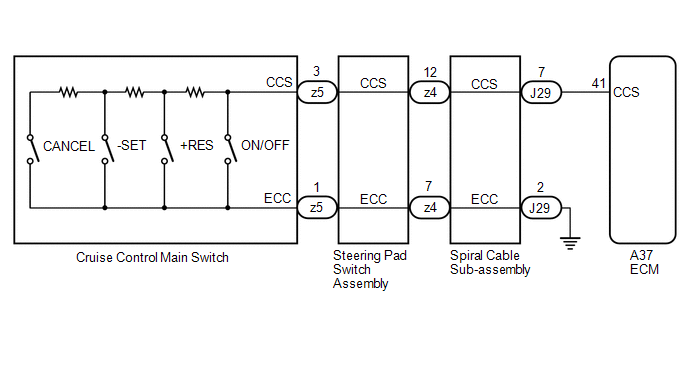
WIRING DIAGRAM
CAUTION / NOTICE / HINT
NOTICE:
-
Before replacing the ECM, refer to Registration.
Click here
.gif)
-
The vehicle is equipped with a Supplemental Restraint System (SRS) which includes components such as airbags. Before servicing (including removal or installation of parts), be sure to read the precaution for Supplemental Restraint System.
Click here
PROCEDURE
| 1. | READ VALUE USING TECHSTREAM |
(a) Connect the Techstream to the DLC3.
(b) Turn the engine switch on (IG).
(c) Turn the Techstream on.
(d) Enter the following menus: Powertrain / Radar Cruise 1 / Data List.
(e) Read the Data List according to the display on the Techstream.
Powertrain > Cruise Control > Data List| Tester Display | Measurement Item | Range | Normal Condition | Diagnostic Note |
|---|---|---|---|---|
| -SET Switch | -SET switch status | OFF or ON | OFF: -SET switch off ON: -SET switch on | - |
| +RES Switch | +RES switch status | OFF or ON | OFF: +RES switch off ON: +RES switch on | - |
| Cruise Main Switch Operation Condition | Cruise control main switch status | OFF or ON | OFF: Cruise control main switch (ON-OFF) off ON: Cruise control main switch (ON-OFF) on | - |
| Tester Display |
|---|
| -SET Switch |
| +RES Switch |
| Cruise Main Switch Operation Condition |
OK:
The Data List items shown in the table change according to the operation of the cruise control main switch.
| OK | .gif) | PROCEED TO NEXT SUSPECTED AREA SHOWN IN PROBLEM SYMPTOMS TABLE |
|
.gif)
| 2. | INSPECT CRUISE CONTROL MAIN SWITCH |
(a) Remove the cruise control main switch.
Click here
(b) Inspect the cruise control main switch.
Click here
| NG | | REPLACE CRUISE CONTROL MAIN SWITCH |
|
| 3. | INSPECT STEERING PAD SWITCH ASSEMBLY |
(a) Remove the steering pad switch assembly.
Click here
(b) Inspect the steering pad switch assembly.
Click here
| NG | | REPLACE STEERING PAD SWITCH ASSEMBLY |
|
| 4. | INSPECT SPIRAL CABLE SUB-ASSEMBLY |
(a) Remove the spiral cable sub-assembly.
Click here
(b) Inspect the spiral cable sub-assembly.
Click here
| NG | | REPLACE SPIRAL CABLE SUB-ASSEMBLY |
|
| 5. | CHECK HARNESS AND CONNECTOR (SPIRAL CABLE SUB-ASSEMBLY - ECM AND BODY GROUND) |
(a) Disconnect the A37 ECM connector.
(b) Measure the resistance according to the value(s) in the table below.
Standard Resistance:
| Tester Connection | Condition | Specified Condition |
|---|---|---|
| J29-7 (CCS) - A37-41 (CCS) | Always | Below 1 Ω |
| J29-2 (ECC) - Body ground | Always | Below 1 Ω |
| J29-7 (CCS) or A37-41 (CCS) - Body ground | Always | 10 kΩ or higher |
| OK | | REPLACE ECM |
| NG | | REPAIR OR REPLACE HARNESS OR CONNECTOR |
 Invalid Data Received from ECM/PCM "A" Invalid Serial Data Received (U040181)
DESCRIPTION If the ECM cannot recognize the forward recognition camera. DTC U040181 is stored. DTC No. Detection Item DTC Detection Condition Trouble Area MIL DTC Output from U040181 ...
 Distance Control Switch Circuit
DESCRIPTION The vehicle-to-vehicle distance control switch is used to set the distance for vehicle-to-vehicle distance control mode. The vehicle-to-vehicle distance control switch is installed in the ...
Other materials:
Lexus RX (RX 350L, RX450h) 2016-2025 Repair Manual > Vehicle Stability Control System: Steering Angle Sensor Module Signal Stuck In Range (C05262A)
DESCRIPTION The skid control ECU (brake actuator assembly) receives signals from the steering angle sensor via CAN communication. HINT: When a malfunction occurs in the communication line to the steering angle sensor, U012687 is output. If a DTC related to the CAN communication line is output, first ...
Lexus RX (RX 350L, RX450h) 2016-2025 Repair Manual > Front Axle Hub: Components
COMPONENTS ILLUSTRATION *A w/o AVS *B w/ AVS *1 FRONT AXLE ASSEMBLY *2 FRONT AXLE SHAFT NUT *3 FRONT DISC *4 FRONT DISC BRAKE CALIPER ASSEMBLY *5 FRONT DRIVE SHAFT ASSEMBLY *6 FRONT LOWER NO. 1 SUSPENSION ARM SUB-ASSEMBLY *7 FRONT SPEED SENSOR *8 TIE ...
Lexus RX (RX 350L, RX450h) 2016-{YEAR} Owners Manual
- For your information
- Pictorial index
- For safety and security
- Instrument cluster
- Operation of each component
- Driving
- Lexus Display Audio system
- Interior features
- Maintenance and care
- When trouble arises
- Vehicle specifications
- For owners
Lexus RX (RX 350L, RX450h) 2016-{YEAR} Repair Manual

0.0461