Lexus RX (RX 350L, RX450h) 2016-2025 Repair Manual: Reassembly
REASSEMBLY
PROCEDURE
1. INSTALL GENERATOR DRIVE END FRAME BEARING
| (a) Using SST and a press, install a new generator drive end frame bearing to the generator drive end frame. SST: 09950-60010 09951-00470 SST: 09950-70010 09951-07100 |
|
| (b) Fit the tabs of the retainer plate into the cutouts of the generator drive end frame to install the retainer plate. |
|
(c) Install the 4 screws.
Torque:
3.0 N·m {31 kgf·cm, 27 in·lbf}
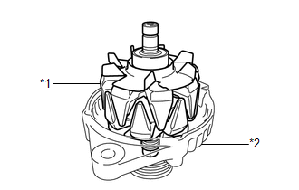
2. INSTALL GENERATOR ROTOR ASSEMBLY
(a) Place the generator drive end frame on the generator pulley with clutch.
| (b) Install the generator rotor assembly to the generator drive end frame. |
|
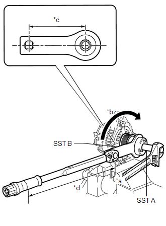
3. INSTALL GENERATOR PULLEY WITH CLUTCH
(a) Temporarily install the generator pulley with clutch to the rotor shaft.
(b) Secure the generator drive end frame in a vise between aluminum plates.
| (c) Place the rotor shaft end into SST (A). SST: 09820-63021 |
|
.png)
(d) Fit SST (B) to the generator pulley with clutch.
| (e) Tighten the generator pulley with clutch by turning SST (B) as shown in the illustration. Torque: Specified tightening torque : 80 N·m {816 kgf·cm, 59 ft·lbf} HINT:
|
|
.gif)
(f) Remove SST (A) and (B) from the generator pulley with clutch.
(g) Check that the generator pulley with clutch rotates smoothly.
(h) Remove the generator drive end frame from the vise.
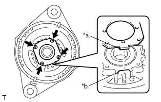
4. INSTALL GENERATOR COIL ASSEMBLY
| (a) Place a new washer on the generator rotor assembly. NOTICE: A washer has direction and must be need to put a washer chip for bearing side. |
|
.png)
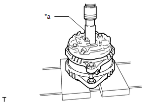
| (b) Using a 21 mm socket wrench and press, slowly press the generator coil assembly to install it. |
|
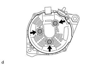
| (c) Install the 4 bolts. Torque: 7.5 N·m {76 kgf·cm, 66 in·lbf} |
|
.png)
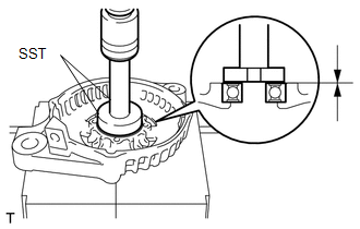
5. INSTALL GENERATOR BRUSH HOLDER ASSEMBLY
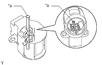
| (a) While pushing the 2 brushes into the generator brush holder assembly, insert a 1.0 mm (0.0394 in.) pin into the generator brush holder assembly hole. |
|
(b) Install the generator brush holder assembly to the generator coil assembly with the 2 screws.
| *a | Pin (1.0 mm) |
.png) | Pull out |
Torque:
1.8 N·m {18 kgf·cm, 16 in·lbf}
(c) Pull out the pin from the generator brush holder assembly hole.
6. INSTALL GENERATOR TERMINAL INSULATOR
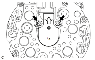
| (a) Install the generator terminal insulator to the generator coil assembly. NOTICE: Be sure to install the generator terminal insulator in the correct direction. |
|
7. INSTALL GENERATOR REAR END COVER
| (a) Install the generator rear end cover to the generator coil assembly with the 3 nuts. Torque: 4.6 N·m {47 kgf·cm, 41 in·lbf} |
|
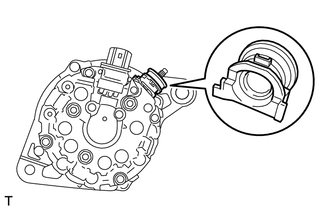
8. INSTALL GENERATOR PULLEY CAP
(a) Install a new generator pulley cap to the generator pulley with clutch.
 Installation
INSTALLATION PROCEDURE 1. INSTALL GENERATOR ASSEMBLY (a) Install the wire harness clamp bracket with the bolt. Torque: 8.4 N·m {86 kgf·cm, 74 in·lbf} (b) Type A: (1) Install the generator assembly ...
 Networking
...
Other materials:
Lexus RX (RX 350L, RX450h) 2016-2025 Repair Manual > Front Seat Outer Belt Assembly: Components
COMPONENTS ILLUSTRATION *A w/o Rear No. 2 Seat *B w/ Rear No. 2 Seat *1 CENTER PILLAR GARNISH ASSEMBLY *2 FRONT DOOR SCUFF PLATE *3 FRONT SEAT OUTER BELT ASSEMBLY *4 FRONT SHOULDER BELT ANCHOR ADJUSTER ASSEMBLY *5 LOWER CENTER PILLAR GARNISH *6 REAR DOOR INSID ...
Lexus RX (RX 350L, RX450h) 2016-2025 Repair Manual > Front Door Opening Trim Weatherstrip: Components
COMPONENTS ILLUSTRATION *1 COWL SIDE TRIM BOARD *2 FRONT DOOR OPENING TRIM WEATHERSTRIP *3 INSTRUMENT PANEL GARNISH - - ...
Lexus RX (RX 350L, RX450h) 2016-{YEAR} Owners Manual
- For your information
- Pictorial index
- For safety and security
- Instrument cluster
- Operation of each component
- Driving
- Lexus Display Audio system
- Interior features
- Maintenance and care
- When trouble arises
- Vehicle specifications
- For owners
Lexus RX (RX 350L, RX450h) 2016-{YEAR} Repair Manual

0.0176