Lexus RX (RX 350L, RX450h) 2016-2025 Repair Manual: Diagnosis System
DIAGNOSIS SYSTEM
CHECK FOR INSTALLED SYSTEMS (ECUS AND SENSORS) THAT USE CAN COMMUNICATION
(a) The systems (ECUs and sensors) that use CAN communication vary depending on the vehicle and optional equipment. Check which systems (ECUs and sensors) are installed to the vehicle.
| Bus | ECU/Sensor Name | Techstream Display | Applicability |
|---|---|---|---|
| V bus | Network gateway ECU | CAN Gateway1 | Installed on all vehicles |
| Bus 1 | Clearance warning ECU assembly | Clearance Warning (Intuitive Parking Assist) | Vehicles with intuitive parking assist system |
| Parking assist ECU | Panoramic View Monitor | Vehicles with panoramic view monitor system | |
| Forward recognition camera | Front Camera Module | Installed on all vehicles | |
| Millimeter wave radar sensor assembly | Front Radar | Installed on all vehicles | |
| Rear television camera assembly | Parking Assist Monitor System | Installed on all vehicles | |
| Blind spot monitor sensor LH | Blind Spot Monitor Master | Vehicles with blind spot monitor system | |
| Bus 2 | ECM | ECM (Engine) | Installed on all vehicles |
| Bus 3 | DCM (telematics transceiver) | DCM | Vehicles with manual (SOS) switch |
| Radio receiver assembly | Display and Navigation (AVN) | Installed on all vehicles | |
| Bus 4 | Skid control ECU (brake actuator assembly) | Skid Control (ABS/VSC/TRAC) | Installed on all vehicles |
| 4WD ECU assembly | Four Wheel Drive Control | Vehicles for AWD | |
| Tire pressure warning ECU and receiver | Tire Pressure | Installed on all vehicles | |
| Absorber control ECU | Suspension Control (Air Suspension) | Vehicles with AVS | |
| Power steering ECU assembly | Power Steering (EPS) | Installed on all vehicles | |
| Steering sensor | Spiral cable (Steering Angle Sensor) | Installed on all vehicles | |
| Occupant detection ECU | Occupant Detection | Installed on all vehicles | |
| Yaw rate sensor assembly | Yaw Rate Sensor | Vehicles with TFT meter type combination meter assembly | |
| Airbag sensor assembly | Airbag | Installed on all vehicles | |
| Bus 5 | Certification ECU (smart key ECU assembly) | Certification (Smart) | Installed on all vehicles |
| Combination meter mirror ECU (headup display) | Head Up Display | Vehicles with headup display system | |
| Headlight ECU sub-assembly LH | Headlight swivel (AFS) | Vehicles with automatic headlight beam level control system | |
| Combination meter assembly | Combination Meter | Installed on all vehicles | |
| Air conditioning amplifier assembly | Air Conditioning Amplifier | Installed on all vehicles | |
| Main body ECU (multiplex network body ECU) | Main Body | Installed on all vehicles | |
| Sub bus 1 | Outer mirror control ECU assembly (for front passenger side) | Outer Mirror Control (R Seat) | Installed on all vehicles |
| Outer mirror control ECU assembly (for driver side) | Outer Mirror Control (L Seat) | Installed on all vehicles | |
| Position control ECU and switch assembly LH | D-Seat | Vehicles with seat position memory system | |
| Multiplex tilt and telescopic ECU | Multiplex Tilt and Telescopic | Installed on all vehicles | |
| Multiplex network door ECU | Back Door | Installed on all vehicles | |
| Main body ECU (multiplex network body ECU) | - | Installed on all vehicles |
HINT:
The names of ECUs and sensors shown on the Techstream display may differ from those shown in the DTC Table by ECU section.
CAN BUS CHECK
HINT:
The ECUs and sensors that are properly connected to the CAN communication system can be displayed using the Techstream.
(a) Using the Techstream, select the CAN Bus Check screen.
NOTICE:
- It may be possible to select buses that do not have ECUs or sensors from the bus selection pull-down menu. This is not a malfunction. (This occurs when optional devices are not on a sub bus that is monitored by a gateway function equipped ECU.)
-
In the bus selection pull down menu, all buses applicable to the model are displayed (e.g. LIN communication buses are also displayed). Therefore, refer to the wiring diagrams to check the names of sub buses for CAN communication.
Click here
.gif)
HINT:
Different connection statuses are indicated by the background color of ECUs and sensors that are displayed.
Explanation of CAN Bus Check Screen| Bus Type | Background Color | Connection Status |
|---|---|---|
| Bus 2 | White | Communication has been normal since the start of the CAN bus check. |
| Yellow | Communication stop occurred at least once since the start of the CAN bus check, but communication is currently occurring (unstable communication). | |
| Red | Communication was established at least once since the start of the CAN bus check, but communication is currently not occurring (unstable communication). | |
| Not displayed | Communication stop has continued since the start of the CAN bus check.*1 | |
| Non-bus 2 (gateway function equipped ECU that does not have history of connected ECUs)*2 | White | Communication has been normal since the start of the CAN bus check. |
| Yellow | Communication stop occurred at least once since the start of the CAN bus check, but communication is currently occurring (unstable communication). | |
| Red | Communication was established at least once since the start of the CAN bus check, but communication is currently not occurring (unstable communication). | |
| Not displayed | Communication stop has continued since the start of the CAN bus check.*1 | |
| Non-bus 2 (gateway function equipped ECU that has history of connected ECUs)*3 | White | Communication has been normal since the start of the CAN bus check. |
| Yellow | Communication stop occurred at least once since the start of the CAN bus check, but communication is currently occurring (unstable communication). | |
| Red | Currently not communicating (either of the following):
| |
| Not displayed | Either of the following:
|
HINT:
- Gateway function equipped ECUs relay signals between the ECUs connected to the different buses.
- *1: ECUs that are present in the vehicle but are not displayed on the CAN Bus Check screen.
- *2: Gateway function equipped ECU that does not memorize the non-bus 2 ECUs that are connected to it.
- *3: Gateway function equipped ECU that memorizes the non-bus 2 ECUs that are connected to it.
- If none of the connected ECUs are displayed, or there is no response from the vehicle to the Techstream, check the central gateway ECU and the V bus branch lines for a malfunction.
(b) Observe the connection response screen for approximately 2 minutes to check for a change in connection status of the connected ECUs and sensors.
HINT:
- If an open occurs in one of the lines of a CAN branch (except DLC3), output from the other branch line (the line that is not open) will be unstable and it may interfere with the response (display) of other ECUs and sensors.
- If the connection status changes during the inspection, repair the open in the branch line of the ECU or sensor that does not respond (is not detected) and then perform the CAN bus check again.
HOW TO INTERPRET CAN BUS CHECK SCREEN
(a) When a communication stop is currently occurring, the probable malfunctioning part can be determined from the CAN bus check and by using the following methods.
NOTICE:
The following CAN bus wiring diagram is provided only as an example. This wiring diagram is different from the actual wiring diagram for this vehicle.
HINT:
- When a communication stop is currently occurring, it is easier to determine the probable malfunctioning part from the CAN bus check rather than from communication DTCs.
- Wait for approximately 2 minutes after turning the engine switch on (IG) (or simulating the driving conditions that enable the malfunction to be reproduced) and select "CAN Bus Check". Then observe the communication status of each ECU on the screen.
(b) If a communication error of only 1 ECU or sensor is indicated on the CAN Bus Check screen, a communication stop of the ECU or sensor is suspected.
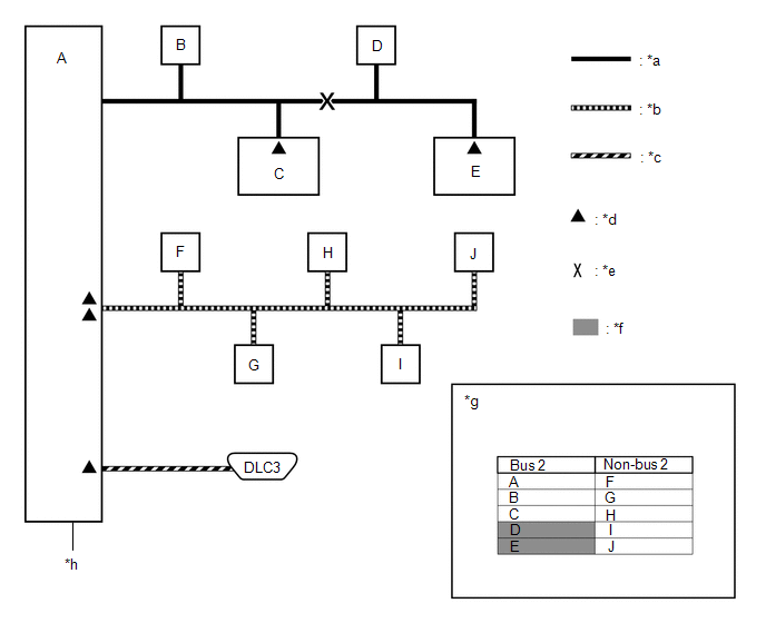
Open in both CAN branch lines of ECU D on the bus 2
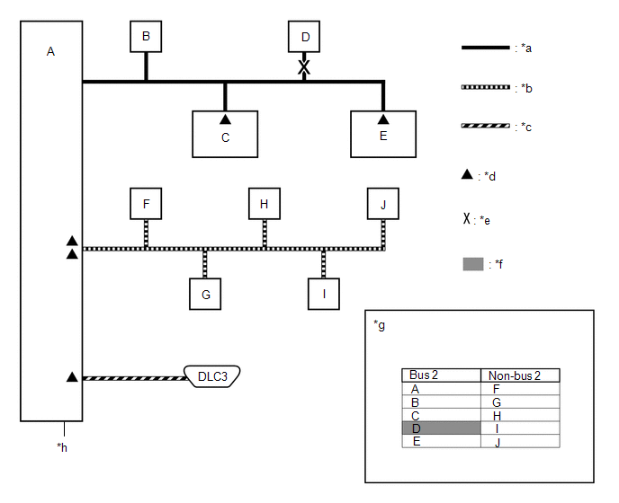
| *a | Bus 2 | *b | Non-bus 2 |
| *c | V Bus | *d | Terminating Resistor |
| *e | Location of Malfunction | *f | Not displayed or background color changes to red or yellow |
| *g | CAN Bus Check Screen | *h | Network Gateway ECU |
HINT:
When there are communication stops, ECUs that are present in the vehicle may not be displayed on the CAN Bus Check screen.
(c) If communication errors for multiple ECUs or sensors are indicated on the CAN Bus Check screen, then a communication stop of the ECU or sensor that shows a more serious communication stop (an ECU or sensor which is not displayed) is suspected.
Example: Open in a CAN branch line for ECU B on the bus 2
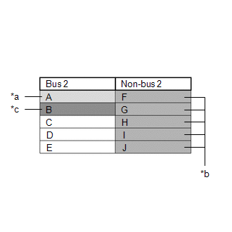
| *a | Background color periodically changes to yellow or red |
| *b | Not displayed or background color is yellow or red |
| *c | Not displayed |
| Bus Type | Background Color | Connection Status |
|---|---|---|
| Bus 2 | White | Communication has been normal since the start of the CAN bus check. |
| Yellow | Communication stop occurred at least once since the start of the CAN bus check, but communication is currently occurring (unstable communication). | |
| Red | Communication was established at least once since the start of the CAN bus check, but communication is currently not occurring (unstable communication). | |
| Not displayed | Communication stop has continued since the start of the CAN bus check.*1 | |
| Non-bus 2 (gateway function equipped ECU that does not have history of connected ECUs)*2 | White | Communication has been normal since the start of the CAN bus check. |
| Yellow | Communication stop occurred at least once since the start of the CAN bus check, but communication is currently occurring (unstable communication). | |
| Red | Communication was established at least once since the start of the CAN bus check, but communication is currently not occurring (unstable communication). | |
| Not displayed | Communication stop has continued since the start of the CAN bus check.*1 | |
| Non-bus 2 (gateway function equipped ECU that has history of connected ECUs)*3 | White | Communication has been normal since the start of the CAN bus check. |
| Yellow | Communication stop occurred at least once since the start of the CAN bus check, but communication is currently occurring (unstable communication). | |
| Red | Currently not communicating (either of the following):
| |
| Not displayed | Either of the following:
|
HINT:
- Gateway function equipped ECUs relay signals between the ECUs connected to the different buses.
- *1: ECUs that are present in the vehicle but are not displayed on the CAN Bus Check screen.
- *2: Gateway function equipped ECU that does not memorize the non-bus 2 ECUs that are connected to it.
- *3: Gateway function equipped ECU that memorizes the non-bus 2 ECUs that are connected to it.
- The example of the CAN Bus Check screen in the illustration shows the result of electrical noise on the CAN bus which is caused by an open in a CAN branch line of ECU B (output from the other branch line is unstable) and the communication of ECU A is also unstable. In addition, in this example, ECU A is equipped with a gateway function. Therefore, communication is also unstable between the non-bus 2 ECUs of ECU A and the bus 2.
- The example in the illustration shows that ECU B is not displayed on the CAN Bus Check screen. This indicates a more significant communication stop. In this case, a communication stop of ECU B is suspected.
(d) If a communication error is indicated on both the bus 2 and non-bus 2 on the CAN Bus Check screen, suspect any communication stop displayed for the bus 2 first.
Example: Open in both CAN branch lines of ECU A on the bus 2
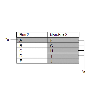
| *a | Not displayed or background color changes to red |
HINT:
- In the CAN bus check, it is possible to confirm the communication status of ECUs connected to the bus 2 after connecting the Techstream to the DLC3. As for non-bus 2, it is possible to confirm which non-bus 2 connected ECUs can communicate with a gateway function equipped ECU on the bus 2.
- If a gateway function equipped ECU has a communication error, ECUs connected to the gateway function equipped ECU are also affected, and communication stops will be indicated.
- The CAN Bus Check screen in the illustration shows that ECU A has a gateway function and a communication stop in ECU A is suspected.
(e) If the CAN Bus Check screen indicates a communication stop only in the non-bus 2, a communication stop in the non-bus 2 is suspected.
Example: Open in both CAN branch lines of ECU G on the non-bus 2
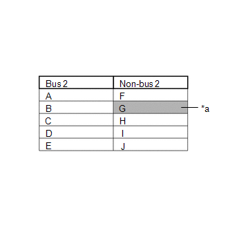
| *a | Background color changes to red |
HINT:
- A communication error in a non-bus 2 does not affect the bus 2 or other buses.
- When a gateway function equipped ECU has memorized the ECUs that are connected to the non-bus 2, if any of the ECUs connected to the gateway function equipped ECU has a communication error, the background color changes to yellow or red. (The displayed name will not disappear.)
(f) If both of the bus 2 main bus lines are open, ECUs or sensors that are located farther away from the network gateway ECU than the open part will be displayed as a communication stop on the CAN Bus Check screen.
(In this case, ECU D and E are not displayed or their background color changes to red.)
| *a | Bus 2 | *b | Non-bus 2 |
| *c | V Bus | *d | Terminating Resistor |
| *e | Location of Malfunction | *f | Not displayed or background color is red |
| *g | CAN Bus Check Screen | *h | Network Gateway ECU |
HINT:
If a communication error occurs in an ECU, it is not displayed on the CAN Bus Check screen even though the ECU is present.
(g) If both of the non-bus 2 main bus lines are open, ECUs that are located farther away from the network gateway ECU than the open part will be displayed as a communication stop on the CAN Bus Check screen.
(In this case, ECU I and J are not displayed or their background color changes to red.)
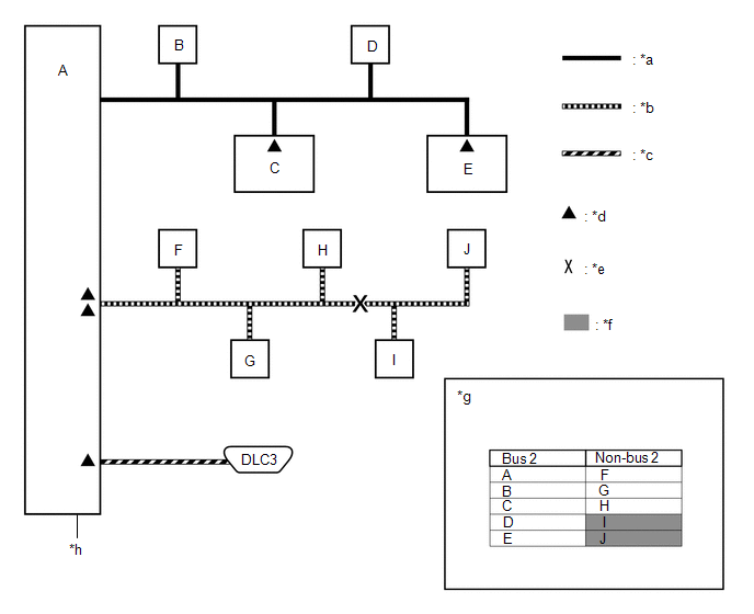
| *a | Bus 2 | *b | Non-bus 2 |
| *c | V Bus | *d | Terminating Resistor |
| *e | Location of Malfunction | *f | Not displayed or background color is red |
| *g | CAN Bus Check Screen | *h | Network Gateway ECU |
(h) When any of the following malfunctions occur, CAN communication cannot be established and almost all ECUs and sensors on the bus show a communication error on the CAN Bus Check screen.
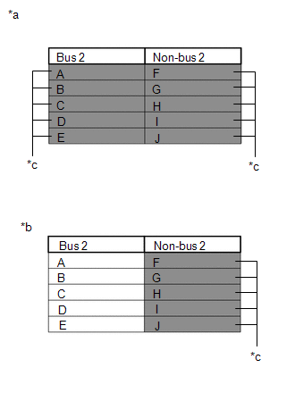
| *a | When any of the following malfunctions occur on the bus 2 |
| *b | When any of the following malfunctions occur on a non-bus 2 |
| *c | Not displayed |
| Short between CAN lines (CANH and CANL) |
| Short between a CAN line (CANH or CANL) and +B |
| Short between a CAN line (CANH or CANL) and ground |
| Open in a CAN main bus line |
HINT:
- When a malfunction occurs in the bus 2, almost all ECUs and sensors on the bus 2 and non-bus 2 indicate a communication error (almost all ECUs are not displayed). As communication with the gateway function equipped ECU that is connected to the bus 2 stops, communication from the ECUs connected to the non-bus 2 that is monitored by the gateway function equipped ECU also stops (these ECUs are not displayed).
- When a malfunction occurs in a non-bus 2, almost all ECUs connected to the non-bus 2 indicate a communication error.
- A communication error in a non-bus 2 does not affect the bus 2 or other buses.
- The malfunctioning part can be determined by checking for a short circuit between CAN bus lines or between a CAN bus line and ground or +B short using an electrical tester.
DTC TABLE BY ECU
HINT:
- In the CAN communication system, the CAN communication DTCs of each ECU can be displayed using the Techstream.
-
If CAN communication system DTCs are output, the malfunction cannot be determined only by the DTCs. Perform troubleshooting according to How to Proceed with Troubleshooting.
Click here
- If the system function temporarily returns to normal, DTCs may not be output again even if the following DTC check procedures are used.
(a) ECM / Techstream Display "Engine"
Powertrain > Engine > Trouble CodesHINT:
- This ECU uses the CAN communication system for DTC communication.
-
*: Refer to SFI System.
Click here
| DTC | Detection Item | DTC Detection Condition | DTC Detection Pre-condition | DTC Check Procedure | Warning Indication in Meter | Multi-information Display | DTC Storage Method |
|---|---|---|---|---|---|---|---|
| U010187* | Lost Communication with TCM Missing Message | The ECM does not receive data from the TCM for 1.25 seconds or more. | Both conditions are met:
| Turn the engine switch on (IG) and wait for at least 2.25 seconds. | MIL illuminates. | - | DTC is stored until it is cleared using the Techstream. |
| U010487 | Lost Communication with Cruise Control Module Missing Message | The ECM does not receive data from the forward recognition camera for 1.02 seconds or more. | Both conditions are met:
| Drive the vehicle at a speed of 40 km/h (25 mph) or more with the cruise control main switch on and operate the dynamic radar cruise control system for 3.12 seconds or more. | - | Displays messages on the multi-information display. | DTC is stored until it is cleared using the Techstream. |
| U015587 | Lost Communication with Instrument Panel Cluster (IPC) Control Module Missing Message | The ECM does not receive data from the combination meter assembly for 3 seconds or more. | Both conditions are met:
| Turn the engine switch on (IG) and wait for at least 6 seconds. | MIL illuminates. | - | DTC is stored until it is cleared using the Techstream. |
(b) ECM / Techstream Display "Transmission"
Powertrain > Transmission > Trouble CodesHINT:
- This ECU uses the CAN communication system for DTC communication.
-
*: Refer to Automatic Transaxle System.
- Click here
(for U881E Automatic Transaxle)- Click here
(for U881F Automatic Transaxle)
| DTC | Detection Item | DTC Detection Condition | DTC Detection Pre-condition | DTC Check Procedure | Warning Indication in Meter | Multi-information Display | DTC Storage Method |
|---|---|---|---|---|---|---|---|
| U010087* | Lost Communication with ECM/PCM "A" Missing Message | The TCM does not receive data from the ECM for 1.25 seconds or more. | Both conditions are met:
| Turn the engine switch on (IG) and wait for at least 2.25 seconds. | MIL illuminates. | - | DTC is stored until it is cleared using the Techstream. |
(c) ECM / Techstream Display "Radar Cruise1"
Powertrain > Cruise Control > Trouble CodesHINT:
This ECU uses the CAN communication system for DTC communication.
ECM / Techstream Display "Radar Cruise1"| DTC | Detection Item | DTC Detection Condition | DTC Detection Pre-condition | DTC Check Procedure | Warning Indication in Meter | Multi-information Display | DTC Storage Method |
|---|---|---|---|---|---|---|---|
| U010087 | Lost Communication with ECM/PCM "A" Missing Message | The skid control ECU (brake actuator assembly) does not receive data from the ECM for 1 second or more. | All conditions are met:
| Drive the vehicle at a speed of 25 km/h (16 mph) or more with the cruise control main switch on for 3 seconds or more. | - | Displays messages on the multi-information display. | DTC is stored until it is cleared using the Techstream. |
| U010487 | Lost Communication with Cruise Control Module Missing Message | The ECM does not receive data from the forward recognition camera for 2 seconds or more. | All conditions are met:
| Drive the vehicle at a speed of 25 km/h (16 mph) or more with the cruise control main switch on for 3 seconds or more. | - | Displays messages on the multi-information display. | DTC is stored until it is cleared using the Techstream. |
| U012287 | Lost Communication with Vehicle Dynamics Control Module Missing Message | The ECM does not receive data from the skid control ECU (brake actuator assembly) for 2.58 seconds or more. | Both conditions are met:
| Turn the cruise control main switch on and wait for at least 2.58 seconds. | - | Displays messages on the multi-information display. | DTC is stored until it is cleared using the Techstream. |
(d) Skid Control ECU (Brake Actuator Assembly) / Techstream Display "Brake/EPB"
Chassis > Brake/EPB > Trouble CodesHINT:
- This ECU uses the CAN communication system for DTC communication.
- *1: w/ TFT Meter Type Combination Meter Assembly
- *2: w/ Optitron Meter Type Combination Meter Assembly
| DTC | Detection Item | DTC Detection Condition | DTC Detection Pre-condition | DTC Check Procedure | Warning Indication in Meter | Multi-information Display | DTC Storage Method |
|---|---|---|---|---|---|---|---|
| U007488 | Control Module Communication Bus "B" Off Bus Off | One of the following conditions is met:
| Both conditions are met:
| Turn the engine switch on (IG) and wait for at least 63 seconds. |
| Displays messages on the multi-information display. | DTC is stored until it is cleared using the Techstream. |
| U010087 | Lost Communication with ECM/PCM "A" Missing Message | The skid control ECU (brake actuator assembly) does not receive data from the ECM for 2 seconds or more. | All conditions are met:
| Drive the vehicle at a speed of 15 km/h (9 mph) or more for 5 seconds or more. |
| Displays messages on the multi-information display. | DTC is stored until it is cleared using the Techstream. |
| U010187 | Lost Communication with TCM Missing Message | The skid control ECU (brake actuator assembly) does not receive data from the ECM for 2 seconds or more. | All conditions are met:
| Drive the vehicle at a speed of 15 km/h (9 mph) or more for 5 seconds or more. |
| Displays messages on the multi-information display. | DTC is stored until it is cleared using the Techstream. |
| U012587 | Lost Communication with Multi-axis Acceleration Sensor Module Missing Message | One of the following conditions is met:
| Both conditions are met:
| Turn the engine switch on (IG) and wait for at least 63 seconds. |
| Displays messages on the multi-information display. | DTC is stored until it is cleared using the Techstream. |
| U012687 | Lost Communication with Steering Angle Sensor Module Missing Message | One of the following conditions is met:
| Both conditions are met:
| Turn the engine switch on (IG) and wait for at least 63 seconds. |
| Displays messages on the multi-information display. | DTC is stored until it is cleared using the Techstream. |
| U015187 | Lost Communication with Restraints Control Module Missing Message | The skid control ECU (brake actuator assembly) does not receive data from the airbag sensor assembly for 5 seconds or more. | All conditions are met:
| Drive the vehicle at a speed of 7 km/h (4 mph) or more for 8 seconds or more. | - | Displays messages on the multi-information display. | DTC is stored until it is cleared using the Techstream. |
(e) Power Steering ECU Assembly / Techstream Display "EMPS"
Chassis > EMPS > Trouble CodesHINT:
This ECU uses the CAN communication system for DTC communication.
Power Steering ECU Assembly / Techstream Display "EMPS"| DTC | Detection Item | DTC Detection Condition | DTC Detection Pre-condition | DTC Check Procedure | Warning Indication in Meter | Multi-information Display | DTC Storage Method |
|---|---|---|---|---|---|---|---|
| U0100 | Lost Communication with ECM / PCM "A" | Both conditions are met:
| All conditions are met:
| Drive the vehicle at a speed of 20 km/h (12 mph) or more for 5 minutes or more. | - | - | DTC remains stored only while malfunction is occurring. |
| U0129 | Lost Communication with Brake System Control Module | The power steering ECU assembly does not receive data from the skid control ECU (brake actuator assembly) for 2.34 seconds or more. | Both conditions are met:
| Turn the engine switch on (IG) and wait for at least 5.34 seconds. | EPS warning light illuminates. | - | DTC remains stored only while malfunction is occurring. |
| U023A | Lost Communication with Front Camera Module | The power steering ECU assembly does not receive data from the forward recognition camera for 1.34 seconds or more. | Both conditions are met:
| Turn the engine switch on (IG) and wait for at least 4.34 seconds. | - | - | DTC remains stored only while malfunction is occurring. |
(f) Main Body ECU (Multiplex Network Body ECU) / Techstream Display "Main Body"
Body Electrical > Main Body > Trouble CodesHINT:
This ECU uses the CAN communication system for DTC communication.
Main Body ECU (Multiplex Network Body ECU) / Techstream Display "Main Body"| DTC | Detection Item | DTC Detection Condition | DTC Detection Pre-condition | DTC Check Procedure | Warning Indication in Meter | Multi-information Display | DTC Storage Method |
|---|---|---|---|---|---|---|---|
| U0100 | Lost Communication with ECM / PCM "A" | The main body ECU (multiplex network body ECU) does not receive data from the ECM for 10 seconds or more. | Both conditions are met:
| Turn the engine switch on (IG) and wait for at least 20 seconds. | - | - | DTC is stored until it is cleared using the Techstream. |
| U0101 | Lost Communication with TCM | The main body ECU (multiplex network body ECU) does not receive data from the ECM for 10 seconds or more. | Both conditions are met:
| Turn the engine switch on (IG) and wait for at least 20 seconds. | - | - | DTC is stored until it is cleared using the Techstream. |
| U0120 | Lost Communication with Starter / Generator Control Module | The main body ECU (multiplex network body ECU) does not receive data from the certification ECU (smart key ECU assembly) for 10 seconds or more. | Both conditions are met:
| Turn the engine switch on (IG) and wait for at least 20 seconds. | - | - | DTC is stored until it is cleared using the Techstream. |
| U0129 | Lost Communication with Brake System Control Module | The main body ECU (multiplex network body ECU) does not receive data from the skid control ECU (brake actuator assembly) for 10 seconds or more. | Both conditions are met:
| Turn the engine switch on (IG) and wait for at least 20 seconds. | - | - | DTC is stored until it is cleared using the Techstream. |
| U0151 | Lost Communication with Restraints Control Module | The main body ECU (multiplex network body ECU) does not receive data from the airbag sensor assembly for 10 seconds or more. | Both conditions are met:
| Turn the engine switch on (IG) and wait for at least 20 seconds. | - | - | DTC is stored until it is cleared using the Techstream. |
| U0155 | Lost Communication with Instrument Panel Cluster (IPC) Control Module | The main body ECU (multiplex network body ECU) does not receive data from the combination meter assembly for 10 seconds or more. | Both conditions are met:
| Turn the engine switch on (IG) and wait for at least 20 seconds. | - | - | DTC is stored until it is cleared using the Techstream. |
| U0164 | Lost Communication with HVAC Control Module | The main body ECU (multiplex network body ECU) does not receive data from the air conditioning amplifier assembly for 10 seconds or more. | Both conditions are met:
| Turn the engine switch on (IG) and wait for at least 20 seconds. | - | - | DTC is stored until it is cleared using the Techstream. |
| U0182 | Lost Communication with AFS | The main body ECU (multiplex network body ECU) does not receive data from the headlight ECU sub-assembly LH for 10 seconds or more. | Both conditions are met:
| Turn the engine switch on (IG) and wait for at least 20 seconds. | - | - | DTC is stored until it is cleared using the Techstream. |
| U0199 | Lost Communication with ''Door Control Module A'' | The main body ECU (multiplex network body ECU) does not receive data from the outer mirror control ECU assembly (for front passenger side) for 10 seconds or more. | Both conditions are met:
| Turn the engine switch on (IG) and wait for at least 21 seconds. | - | - | DTC is stored until it is cleared using the Techstream. |
| U0200 | Lost Communication with ''Door Control Module B'' | The main body ECU (multiplex network body ECU) does not receive data from the outer mirror control ECU assembly (for driver side) for 10 seconds or more. | Both conditions are met:
| Turn the engine switch on (IG) and wait for at least 21 seconds. | - | - | DTC is stored until it is cleared using the Techstream. |
| U0208 | Lost Communication with ''Seat Control Module A'' | The main body ECU (multiplex network body ECU) does not receive data from the position control ECU and switch assembly LH for 10 seconds or more. | Both conditions are met:
| Turn the engine switch on (IG) and wait for at least 20 seconds. | - | - | DTC is stored until it is cleared using the Techstream. |
| U0230 | Lost Communication with Rear Gate Module | The main body ECU (multiplex network body ECU) does not receive data from the multiplex network door ECU for 10 seconds or more. | Both conditions are met:
| Turn the engine switch on (IG) and wait for at least 20 seconds. | - | - | DTC is stored until it is cleared using the Techstream. |
| U023A | Lost Communication with Image Processing Module "A" | The main body ECU (multiplex network body ECU) does not receive data from the forward recognition camera for 10 seconds or more. | Both conditions are met:
| Turn the engine switch on (IG) and wait for at least 20 seconds. | - | - | DTC is stored until it is cleared using the Techstream. |
| U0265 | Lost Communication with Parking Assist Monitor Module | The main body ECU (multiplex network body ECU) does not receive data from the rear television camera assembly for 10 seconds or more. | Both conditions are met:
| Turn the engine switch on (IG) and wait for at least 20 seconds. | - | - | DTC is stored until it is cleared using the Techstream. |
| U0327 | Software Incompatibility with Vehicle Security Control Module | The main body ECU (multiplex network body ECU) does not receive data from the certification ECU (smart key ECU assembly) for 10 seconds or more. | Both conditions are met:
| Turn the engine switch on (IG) and wait for at least 20 seconds. | - | - | DTC is stored until it is cleared using the Techstream. |
| U1002 | Lost Communication with Gateway Module | The main body ECU (multiplex network body ECU) detects communication errors between itself and the position control ECU and switch assembly LH, outer mirror control ECU assembly (for front passenger side), outer mirror control ECU assembly (for driver side), multiplex network door ECU and multiplex tilt and telescopic ECU. | Both conditions are met:
| Turn the engine switch on (IG) and wait for at least 20 seconds. | - | - | DTC is stored until it is cleared using the Techstream. |
| U1106 | Lost Communication with Electric Parking Brake Module | The main body ECU (multiplex network body ECU) does not receive data from the skid control ECU (brake actuator assembly) for 10 seconds or more. | Both conditions are met:
| Turn the engine switch on (IG) and wait at least 20 seconds. | - | - | DTC is stored until it is cleared using the Techstream. |
| U1115 | Lost Communication with Tilt & Telescopic Module | The main body ECU (multiplex network body ECU) does not receive data from the multiplex tilt and telescopic ECU for 10 seconds or more. | Both conditions are met:
| Turn the engine switch on (IG) and wait for at least 20 seconds. | - | - | DTC is stored until it is cleared using the Techstream. |
| U1126 | Lost Communication with Parking Assist Monitor Module | The main body ECU (multiplex network body ECU) does not receive data from the rear television camera assembly for 10 seconds or more. | Both conditions are met:
| Turn the engine switch on (IG) and wait at least 20 seconds. | - | - | DTC is stored until it is cleared using the Techstream. |
(g) Certification ECU (Smart Key ECU Assembly) / Techstream Display "Smart Access"
Body Electrical > Smart Access > Trouble CodesHINT:
This ECU uses the CAN communication system for DTC communication.
Certification ECU (Smart Key ECU Assembly) / Techstream Display "Smart Access"| DTC | Detection Item | DTC Detection Condition | DTC Detection Pre-condition | DTC Check Procedure | Warning Indication in Meter | Multi-information Display | DTC Storage Method |
|---|---|---|---|---|---|---|---|
| U0100 | Lost Communication with ECM / PCM "A" | The certification ECU (smart key ECU assembly) does not receive data from the ECM for 10 seconds or more. | Both conditions are met:
| Turn the engine switch on (IG) and wait for at least 20 seconds. | - | - | DTC is stored until it is cleared using the Techstream. |
| U0142 | Lost Communication with Body Control Module "B" | The certification ECU (smart key ECU assembly) does not receive data from the main body ECU (multiplex network body ECU) for 10 seconds or more. | Both conditions are met:
| Turn the engine switch on (IG) and wait for at least 20 seconds. | - | - | DTC is stored until it is cleared using the Techstream. |
| U0155 | Lost Communication with Instrument Panel Cluster (IPC) Control Module | The certification ECU (smart key ECU assembly) does not receive data from the combination meter assembly for 10 seconds or more. | Both conditions are met:
| Turn the engine switch on (IG) and wait for at least 20 seconds. | - | - | DTC is stored until it is cleared using the Techstream. |
(h) Certification ECU (Smart Key ECU Assembly) / Techstream Display "Power Source Control"
Body Electrical > Power Source Control > Trouble CodesHINT:
This ECU uses the CAN communication system for DTC communication.
Certification ECU (Smart Key ECU Assembly) / Techstream Display "Power Source Control"| DTC | Detection Item | DTC Detection Condition | DTC Detection Pre-condition | DTC Check Procedure | Warning Indication in Meter | Multi-information Display | DTC Storage Method |
|---|---|---|---|---|---|---|---|
| U0100 | ECM Communication | The certification ECU (smart key ECU assembly) does not receive data from the ECM for 3.1 seconds or more. | Both conditions are met:
| Turn the engine switch on (IG) and wait for at least 3.1 seconds. | - | - | DTC is stored until it is cleared using the Techstream. |
| U0140 | Lost Communication with Body Control Module | The certification ECU (smart key ECU assembly) does not receive data from the main body ECU (multiplex network body ECU) for 3 seconds or more. | Both conditions are met:
| Turn the engine switch on (IG) and wait for at least 3 seconds. | - | - | DTC is stored until it is cleared using the Techstream. |
| U0155 | Lost Communication with Instrument Panel Cluster (IPC) Control Module | The certification ECU (smart key ECU assembly) does not receive data from the combination meter assembly for 3.1 seconds or more. | Both conditions are met:
| Turn the engine switch on (IG) and wait for at least 3.1 seconds. | - | - | DTC is stored until it is cleared using the Techstream. |
(i) Certification ECU (Smart Key ECU Assembly) / Techstream Display "Starting Control"
Body Electrical > Starting Control > Trouble CodesHINT:
This ECU uses the CAN communication system for DTC communication.
Certification ECU (Smart Key ECU Assembly) / Techstream Display "Starting Control"| DTC | Detection Item | DTC Detection Condition | DTC Detection Pre-condition | DTC Check Procedure | Warning Indication in Meter | Multi-information Display | DTC Storage Method |
|---|---|---|---|---|---|---|---|
| U0100 | Lost Communication with ECM / PCM "A" | The certification ECU (smart key ECU assembly) does not receive data from the ECM for 2 seconds or more. | Both conditions are met:
| Turn the engine switch on (IG) and wait for at least 2 seconds. | - | - | DTC is stored until it is cleared using the Techstream. |
(j) Air Conditioning Amplifier Assembly / Techstream Display "Air Conditioner"
Body Electrical > Air Conditioner > Trouble CodesHINT:
This ECU uses the CAN communication system for DTC communication.
Air Conditioning Amplifier Assembly / Techstream Display "Air Conditioner"| DTC | Detection Item | DTC Detection Condition | DTC Detection Pre-condition | DTC Check Procedure | Warning Indication in Meter | Multi-information Display | DTC Storage Method |
|---|---|---|---|---|---|---|---|
| U0100 | Lost Communication with ECM / PCM "A" | The air conditioning amplifier assembly does not receive data from the ECM for 7.5 seconds or more. | Both conditions are met:
| Turn the engine switch on (IG) and wait for at least 7.5 seconds. | - | - | DTC is stored until it is cleared using the Techstream. |
| U0131 | Lost Communication with Power Steering Control Module | The air conditioning amplifier assembly does not receive data from the power steering ECU assembly for 5 seconds or more. | Both conditions are met:
| Turn the engine switch on (IG) and wait for at least 5 seconds. | - | - | DTC is stored until it is cleared using the Techstream. |
| U0142 | Lost Communication with Body Control Module "B" | The air conditioning amplifier assembly does not receive data from the main body ECU (multiplex network body ECU) for 5 seconds or more. | Both conditions are met:
| Turn the engine switch on (IG) and wait for at least 5 seconds. | - | - | DTC is stored until it is cleared using the Techstream. |
| U0151 | Lost Communication with Restraints Control Module | The air conditioning amplifier assembly does not receive data from the airbag sensor assembly for 5 seconds or more. | Both conditions are met:
| Turn the engine switch on (IG) and wait for at least 5 seconds. | - | - | DTC is stored until it is cleared using the Techstream. |
| U0155 | Lost Communication with Instrument Panel Cluster (IPC) Control Module | The air conditioning amplifier assembly does not receive data from the combination meter assembly for 5 seconds or more. | Both conditions are met:
| Turn the engine switch on (IG) and wait for at least 5 seconds. | - | - | DTC is stored until it is cleared using the Techstream. |
| U0163 | Lost Communication with Navigation Control Module | The air conditioning amplifier assembly does not receive data from the radio receiver assembly for 5 seconds or more. | Both conditions are met:
| Turn the engine switch on (IG) and wait for at least 5 seconds. | - | - | DTC is stored until it is cleared using the Techstream. |
(k) DCM (Telematics Transceiver) (w/ Manual (SOS) Switch) / Techstream Display "Telematics"
Body Electrical > Telematics > Trouble CodesHINT:
This ECU uses the CAN communication system for DTC communication.
DCM (Telematics Transceiver) / Techstream Display "Telematics"| DTC | Detection Item | DTC Detection Condition | DTC Detection Pre-condition | DTC Check Procedure | Warning Indication in Meter | Multi-information Display | DTC Storage Method |
|---|---|---|---|---|---|---|---|
| U014087 | Lost Communication with Body Control Module Missing Message | The DCM (telematics transceiver) does not receive data from the main body ECU (multiplex network body ECU) for 10 seconds or more. | Both conditions are met:
| Turn the engine switch on (IG) and wait for at least 20 seconds. | - | - | DTC remains stored only while malfunction is occurring. |
| U015587 | Lost Communication with Instrument Panel Cluster (IPC) Control Module Missing Message | The DCM (telematics transceiver) does not receive data from the combination meter assembly for 10 seconds or more. | Both conditions are met:
| Turn the engine switch on (IG) and wait for at least 20 seconds. | - | - | DTC remains stored only while malfunction is occurring. |
| U016387 | Lost Communication with Navigation Control Module Missing Message | The DCM (telematics transceiver) does not receive data from the radio receiver assembly for 10 seconds or more. | Both conditions are met:
| Turn the engine switch on (IG) and wait for at least 20 seconds. | - | - | DTC remains stored only while malfunction is occurring. |
(l) Radio Receiver Assembly (w/ Navigation System) / Techstream Display "Navigation System"
Body Electrical > Navigation System > Trouble CodesHINT:
This ECU uses the CAN communication system for DTC communication.
Radio Receiver Assembly / Techstream Display "Navigation System"| DTC | Detection Item | DTC Detection Condition | DTC Detection Pre-condition | DTC Check Procedure | Warning Indication in Meter | Multi-information Display | DTC Storage Method |
|---|---|---|---|---|---|---|---|
| U0073 | Sending Malfunction (Navigation to APGS) | The radio and display receiver assembly does not send/receive data. | Both conditions are met:
| Turn the engine switch on (IG) and wait for at least 3 seconds. | - | - | DTC is stored until it is cleared using the Techstream. |
| U0100 | Engine ECU Communication | The radio receiver assembly does not receive data from the ECM for 10 seconds or more. | Both conditions are met:
| Turn the engine switch on (IG) and wait for at least 13 seconds. | - | - | DTC is stored until it is cleared using the Techstream. |
| U0129 | VSC (ECB) ECU Communication | The radio receiver assembly does not receive data from the skid control ECU (brake actuator assembly) for 10 seconds or more. | Both conditions are met:
| Turn the engine switch on (IG) and wait for at least 13 seconds. | - | - | DTC is stored until it is cleared using the Techstream. |
| U0140 | Lost Communication with Body Control Module | The radio receiver assembly does not receive data from the main body ECU (multiplex network body ECU) for 10 seconds or more. | Both conditions are met:
| Turn the engine switch on (IG) and wait for at least 13 seconds. | - | - | DTC is stored until it is cleared using the Techstream. |
| U0155 | Meter ECU Communication | The radio receiver assembly does not receive data from the combination meter assembly for 30 seconds or more. | Both conditions are met:
| Turn the engine switch on (IG) and wait for at least 33 seconds. | - | - | DTC is stored until it is cleared using the Techstream. |
| U0164 | Air Conditioner ECU Communication | The radio receiver assembly does not receive data from the air conditioning amplifier assembly for 10 seconds or more. | Both conditions are met:
| Turn the engine switch on (IG) and wait for at least 13 seconds. | - | - | DTC is stored until it is cleared using the Techstream. |
| U0198 | Lost Communication with Telematic Control Module | The radio receiver assembly does not receive data from the DCM (telematics transceiver) for 3 seconds or more. | Both conditions are met:
| Turn the engine switch on (IG) and wait for at least 6 seconds. | - | - | DTC is stored until it is cleared using the Techstream. |
| U023B | Lost Communication with Image Processing Module "B" | The radio receiver assembly does not receive data from the parking assist ECU for 12 seconds or more. | Both conditions are met:
| Turn the engine switch on (IG) and wait for at least 15 seconds. | - | - | DTC is stored until it is cleared using the Techstream. |
| U0265 | Lost Communication with Image Processing Sensor A | The radio receiver assembly does not receive data from the rear television camera assembly for 11.1 seconds or more. | Both conditions are met:
| Turn the engine switch on (IG) and wait for at least 14.1 seconds. | - | - | DTC is stored until it is cleared using the Techstream. |
| U1110 | Clearance Sonar ECU Communication | The radio receiver assembly does not receive data from the clearance warning ECU assembly for 10 seconds or more. | Both conditions are met:
| Turn the engine switch on (IG) and wait for at least 13 seconds. | - | - | DTC is stored until it is cleared using the Techstream. |
(m) Radio Receiver Assembly (w/ Audio and Visual System) / Techstream Display "Navigation System"
Body Electrical > Navigation System > Trouble CodesHINT:
This ECU uses the CAN communication system for DTC communication.
Radio Receiver Assembly / Techstream Display "Navigation System"| DTC | Detection Item | DTC Detection Condition | DTC Detection Pre-condition | DTC Check Procedure | Warning Indication in Meter | Multi-information Display | DTC Storage Method |
|---|---|---|---|---|---|---|---|
| U0073 | Sending Malfunction (Navigation to APGS) | The radio and display receiver assembly does not send/receive data. | Both conditions are met:
| Turn the engine switch on (IG) and wait for at least 3 seconds. | - | - | DTC is stored until it is cleared using the Techstream. |
| U0100 | Engine ECU Communication | The radio receiver assembly does not receive data from the ECM for 10 seconds or more. | Both conditions are met:
| Turn the engine switch on (IG) and wait for at least 13 seconds. | - | - | DTC is stored until it is cleared using the Techstream. |
| U0129 | VSC (ECB) ECU Communication | The radio receiver assembly does not receive data from the skid control ECU (brake actuator assembly) for 10 seconds or more. | Both conditions are met:
| Turn the engine switch on (IG) and wait for at least 13 seconds. | - | - | DTC is stored until it is cleared using the Techstream. |
| U0140 | Lost Communication with Body Control Module | The radio receiver assembly does not receive data from the main body ECU (multiplex network body ECU) for 10 seconds or more. | Both conditions are met:
| Turn the engine switch on (IG) and wait for at least 13 seconds. | - | - | DTC is stored until it is cleared using the Techstream. |
| U0155 | Meter ECU Communication | The radio receiver assembly does not receive data from the combination meter assembly for 30 seconds or more. | Both conditions are met:
| Turn the engine switch on (IG) and wait for at least 33 seconds. | - | - | DTC is stored until it is cleared using the Techstream. |
| U0164 | Air Conditioner ECU Communication | The radio receiver assembly does not receive data from the air conditioning amplifier assembly for 10 seconds or more. | Both conditions are met:
| Turn the engine switch on (IG) and wait for at least 13 seconds. | - | - | DTC remains stored only while malfunction is occurring. |
| U0198 | Lost Communication with Telematic Control Module | The radio receiver assembly does not receive data from the DCM (telematics transceiver) for 3 seconds or more. | Both conditions are met:
| Turn the engine switch on (IG) and wait for at least 6 seconds. | - | - | DTC is stored until it is cleared using the Techstream. |
| U0265 | Lost Communication with Image Processing Sensor A | The radio receiver assembly does not receive data from the rear television camera assembly for 11.1 seconds or more. | Both conditions are met:
| Turn the engine switch on (IG) and wait for at least 14.1 seconds. | - | - | DTC is stored until it is cleared using the Techstream. |
| U1110 | Clearance Sonar ECU Communication | The radio receiver assembly does not receive data from the clearance warning ECU assembly for 10 seconds or more. | Both conditions are met:
| Turn the engine switch on (IG) and wait for at least 13 seconds. | - | - | DTC is stored until it is cleared using the Techstream. |
(n) Combination Meter Assembly / Techstream Display "Combination Meter"
Body Electrical > Combination Meter > Trouble CodesHINT:
This ECU uses the CAN communication system for DTC communication.
Combination Meter Assembly / Techstream Display "Combination Meter"| DTC | Detection Item | DTC Detection Condition | DTC Detection Pre-condition | DTC Check Procedure | Warning Indication in Meter | Multi-information Display | DTC Storage Method |
|---|---|---|---|---|---|---|---|
| U0100 | Lost Communication with ECM / PCM "A" | The combination meter assembly does not receive data from the ECM for 2 seconds or more. | Both conditions are met:
| Turn the engine switch on (IG) and wait for at least 2 seconds. | MIL illuminates. | - | DTC is stored until it is cleared using the Techstream. |
| U0129 | Lost Communication with Brake System Control Module | The combination meter assembly does not receive data from the skid control ECU (brake actuator assembly) for 3 seconds or more. | Both conditions are met:
| Turn the engine switch on (IG) and wait for at least 3 seconds. |
| - | DTC is stored until it is cleared using the Techstream. |
| U0131 | Lost Communication with Power Steering Control Module | The combination meter assembly does not receive data from the power steering ECU assembly for 3 seconds or more. | Both conditions are met:
| Turn the engine switch on (IG) and wait for at least 3 seconds. | EPS warning light illuminates. | - | DTC is stored until it is cleared using the Techstream. |
| U0140 | Lost Communication with Body Control Module | The combination meter assembly does not receive data from the main body ECU (multiplex network body ECU) for 10 seconds or more. | Both conditions are met:
| Turn the engine switch on (IG) and wait for at least 10 seconds. | - | - | DTC is stored until it is cleared using the Techstream. |
| U0151 | Lost Communication with Restraints Control Module | The combination meter assembly does not receive data from the airbag sensor assembly for 10 seconds or more. | Both conditions are met:
| Turn the engine switch on (IG) and wait for at least 10 seconds. | SRS warning light illuminates. | - | DTC is stored until it is cleared using the Techstream. |
| U0163 | Lost Communication with Navigation Control Module | The combination meter assembly does not receive data from the radio receiver assembly for 3 seconds or more. | Both conditions are met:
| Turn the engine switch on (IG) and wait for at least 3 seconds. | - | - | DTC is stored until it is cleared using the Techstream. |
| U0182 | Lost Communication with Lighting Control Module Front | The combination meter assembly does not receive data from the headlight ECU sub-assembly LH for 10 seconds or more. | Both conditions are met:
| Turn the engine switch on (IG) and wait for at least 10 seconds. | Displays messages on the multi-information display. | - | DTC is stored until it is cleared using the Techstream. |
| U023A | Lost Communication with Front Camera Module | The combination meter assembly does not receive data from the forward recognition camera for 10 seconds or more. | Both conditions are met:
| Turn the engine switch on (IG) and wait for at least 10 seconds. | - | - | DTC is stored until it is cleared using the Techstream. |
(o) Outer Mirror Control ECU Assembly (for Front Passenger Side) / Techstream Display "Mirror R"
Body Electrical > Mirror R > Trouble CodesHINT:
This ECU uses the CAN communication system for DTC communication.
Outer Mirror Control ECU Assembly (for Front Passenger Side) / Techstream Display "Mirror R"| DTC | Detection Item | DTC Detection Condition | DTC Detection Pre-condition | DTC Check Procedure | Warning Indication in Meter | Multi-information Display | DTC Storage Method |
|---|---|---|---|---|---|---|---|
| U0142 | Lost Communication with Body Control Module ''B'' | The outer mirror control ECU assembly (for front passenger side) does not receive data from the main body ECU (multiplex network body ECU) for 10 seconds or more. | Both conditions are met:
| Turn the engine switch on (IG) and wait for at least 20 seconds. | - | - | DTC is stored until it is cleared using the Techstream. |
(p) Outer Mirror Control ECU Assembly (for Driver Side) / Techstream Display "Mirror L"
Body Electrical > Mirror L > Trouble CodesHINT:
This ECU uses the CAN communication system for DTC communication.
Outer Mirror Control ECU Assembly (for Driver Side) / Techstream Display "Mirror L"| DTC | Detection Item | DTC Detection Condition | DTC Detection Pre-condition | DTC Check Procedure | Warning Indication in Meter | Multi-information Display | DTC Storage Method |
|---|---|---|---|---|---|---|---|
| U0142 | Lost Communication with Body Control Module ''B'' | The outer mirror control ECU assembly (for driver side) does not receive data from the main body ECU (multiplex network body ECU) for 10 seconds or more. | Both conditions are met:
| Turn the engine switch on (IG) and wait for at least 20 seconds. | - | - | DTC is stored until it is cleared using the Techstream. |
(q) Multiplex Tilt and Telescopic ECU / Techstream Display "Tilt & Telescopic"
Body Electrical > Tilt&Telescopic > Trouble CodesHINT:
This ECU uses the CAN communication system for DTC communication.
Multiplex Tilt and Telescopic ECU / Techstream Display "Tilt & Telescopic"| DTC | Detection Item | DTC Detection Condition | DTC Detection Pre-condition | DTC Check Procedure | Warning Indication in Meter | Multi-information Display | DTC Storage Method |
|---|---|---|---|---|---|---|---|
| U0142 | Lost Communication with Body ECU | The multiplex tilt and telescopic ECU does not receive data from the main body ECU (multiplex network body ECU) for 10 seconds or more. | Both conditions are met:
| Turn the engine switch on (IG) and wait for at least 20 seconds. | - | - | DTC remains stored only while malfunction is occurring. |
| U0208 | Lost Communication with D-Seat ECU | The multiplex tilt and telescopic ECU does not receive data from the position control ECU and switch assembly LH for 10 seconds or more. | Both conditions are met:
| Turn the engine switch on (IG) and wait for at least 20 seconds. | - | - | DTC remains stored only while malfunction is occurring. |
(r) Absorber Control ECU (w/ AVS) / Techstream Display "Air suspension"
Chassis > Air suspension > Trouble CodesHINT:
- This ECU uses the CAN communication system for DTC communication.
- *1:w/ TFT Meter Type Combination Meter Assembly
- *2:w/ Optitron Meter Type Combination Meter Assembly
| DTC | Detection Item | DTC Detection Condition | DTC Detection Pre-condition | DTC Check Procedure | Warning Indication in Meter | Multi-information Display | DTC Storage Method |
|---|---|---|---|---|---|---|---|
| U0100 | Lost Communication with ECM / PCM "A" | The absorber control ECU does not receive data from the ECM for 3 seconds or more. | All conditions are met:
| Drive the vehicle at a speed of 30 km/h (19 mph) or more for 3 seconds or more. | - | - | DTC is stored until it is cleared using the Techstream. |
| U0101 | Lost Communication with TCM | The absorber control ECU does not receive data from the ECM for 6 seconds or more. | All conditions are met:
| Drive the vehicle at a speed of 30 km/h (19 mph) or more for 6 seconds or more. | - | - | DTC is stored until it is cleared using the Techstream. |
| U0122 | Lost Communication with Vehicle Dynamics Control Module | The absorber control ECU does not receive data from the skid control ECU (brake actuator assembly) for 3 seconds or more. | Both conditions are met:
| Turn the engine switch on (IG) and wait for at least 5 seconds. | - | - | DTC is stored until it is cleared using the Techstream. |
| U0124 | Lost Communication with Lateral Acceleration Sensor Module |
| Both conditions are met:
| Turn the engine switch on (IG) and wait for at least 4 seconds. | - | - | DTC is stored until it is cleared using the Techstream. |
| U0126 | Lost Communication with Steering Angle Sensor Module | The absorber control ECU does not receive data from the steering sensor for 3 seconds or more. | Both conditions are met:
| Turn the engine switch on (IG) and wait for at least 4 seconds. | - | - | DTC is stored until it is cleared using the Techstream. |
(s) Clearance Warning ECU Assembly / Techstream Display "Advanced Parking Guidance/ICS/Intuitive P/A"
Body Electrical > Advanced Parking Guidance/ICS/Intuitive P/A > Trouble CodesHINT:
- This ECU uses the CAN communication system for DTC communication.
-
*1: Refer to Intelligent Clearance Sonar System.
Click here
-
*2: Refer to Intuitive Parking Assist System (w/ Intelligent Clearance Sonar System).
Click here
| DTC | Detection Item | DTC Detection Condition | DTC Detection Pre-condition | DTC Check Procedure | Warning Indication in Meter | Multi-information Display | DTC Storage Method |
|---|---|---|---|---|---|---|---|
| U0073 | Control Module Communication Bus "A" Off | Either of the following conditions is met:
| Both conditions are met:
| Turn the engine switch on (IG) and wait for at least 8 seconds. | ICS OFF indicator light blinks. | Displays messages on the multi-information display. | DTC is stored until it is cleared using the Techstream. |
| U0100 | Lost Communication with ECM/PCM "A" | The clearance warning ECU assembly does not receive data from the ECM for 5.12 seconds or more. | Both conditions are met:
| Turn the engine switch on (IG) and wait for at least 8.12 seconds. | ICS OFF indicator light blinks. | Displays messages on the multi-information display. | DTC is stored until it is cleared using the Techstream. |
| U0124 | Lost Communication with Lateral Acceleration Sensor Module | The clearance warning ECU assembly does not receive data from the yaw rate sensor assembly for 0.72 seconds or more. | Both conditions are met:
| Turn the engine switch on (IG) and wait for at least 3.72 seconds. | ICS OFF indicator light blinks. | Displays messages on the multi-information display. | DTC is stored until it is cleared using the Techstream. |
| U0126 | Lost Communication with Steering Angle Sensor Module | The clearance warning ECU assembly does not receive data from the steering sensor for 5.04 seconds or more. | Both conditions are met:
| Turn the engine switch on (IG) and wait for at least 8.04 seconds. | ICS OFF indicator light blinks. | Displays messages on the multi-information display. | DTC is stored until it is cleared using the Techstream. |
| U0129 | Lost Communication with Brake System Control Module | The clearance warning ECU assembly does not receive data from the skid control ECU (brake actuator assembly) for 4.92 seconds or more. | Both conditions are met:
| Turn the engine switch on (IG) and wait for at least 7.92 seconds. | ICS OFF indicator light blinks. | Displays messages on the multi-information display. | DTC is stored until it is cleared using the Techstream. |
| U0140 | Lost Communication with Body Control Module | The clearance warning ECU assembly does not receive data from the main body ECU (multiplex network body ECU) for 5 seconds or more. | Both conditions are met:
| Turn the engine switch on (IG) and wait for at least 8 seconds. | - | - | DTC is stored until it is cleared using the Techstream. |
| U0151 | Lost Communication with Restraints Control Module (Air Bag) | The clearance warning ECU assembly does not receive data from the airbag sensor assembly for 0.72 seconds or more. | Both conditions are met:
| Turn the engine switch on (IG) and wait for at least 3.72 seconds. | ICS OFF indicator light blinks. | Displays messages on the multi-information display. | DTC is stored until it is cleared using the Techstream. |
| U0155 | Lost Communication with Instrument Panel Cluster (IPC) Control Module | The clearance warning ECU assembly does not receive data from the combination meter assembly for 5 seconds or more. | Both conditions are met:
| Turn the engine switch on (IG) and wait for at least 8 seconds. | - | - | DTC is stored until it is cleared using the Techstream. |
| U0164 | Lost Communication with HVAC Control Module | The clearance warning ECU assembly does not receive data from the air conditioning amplifier assembly for 5 seconds or more. | Both conditions are met:
| Turn the engine switch on (IG) and wait for at least 8 seconds. | - | - | DTC is stored until it is cleared using the Techstream. |
| U0232*1 | Lost Communication with Blind Spot Monitor Slave Module | The clearance warning ECU assembly does not receive data from the blind spot monitor sensor RH for 5 seconds or more. | Both conditions are met:
| Turn the engine switch on (IG) and wait for at least 8 seconds. | ICS OFF indicator light blinks. | Displays messages on the multi-information display. | DTC is stored until it is cleared using the Techstream. |
| U0233*1 | Lost Communication with Blind Spot Monitor Master Module | The clearance warning ECU assembly does not receive data from the blind spot monitor sensor LH for 5 seconds or more. | Both conditions are met:
| Turn the engine switch on (IG) and wait for at least 8 seconds. | ICS OFF indicator light blinks. | Displays messages on the multi-information display. | DTC is stored until it is cleared using the Techstream. |
| U1000*2 | CAN Communication Failure (Message Registry) | CAN communication malfunction (message register) | Both conditions are met:
| Turn the engine switch on (IG) and wait for at least 3 seconds. | ICS OFF indicator light blinks. | Displays messages on the multi-information display. | DTC is stored until it is cleared using the Techstream. |
(t) Blind Spot Monitor Sensor LH (w/ Blind Spot Monitor System) / Techstream Display "Blind Spot Monitor Master"
Body Electrical > Blind Spot Monitor Master > Trouble CodesHINT:
- This ECU uses the CAN communication system for DTC communication.
- *1: w/ TFT Meter Type Combination Meter Assembly
- *2: w/ Optitron Meter Type Combination Meter Assembly
-
*3: Refer to Blind Spot Monitor System.
Click here
-
*4: Refer to Blind Spot Monitor System.
Click here
| DTC | Detection Item | DTC Detection Condition | DTC Detection Pre-condition | DTC Check Procedure | Warning Indication in Meter | Multi-information Display | DTC Storage Method |
|---|---|---|---|---|---|---|---|
| U0100 | Lost Communication with ECM / PCM "A" | The blind spot monitor sensor LH does not receive data from the ECM for 10.8 seconds or more. | All conditions are met:
| Drive the vehicle at a speed of 5 km/h (3 mph) or more for 13.8 seconds or more. | - | Displays messages on the multi-information display. | DTC is stored until it is cleared using the Techstream. |
| U0125 | Lost Communication with Yaw Rate Sensor Module |
| All conditions are met:
| Drive the vehicle at a speed of 7 km/h (4 mph) or more for 6.1 seconds or more. | - | Displays messages on the multi-information display. | DTC is stored until it is cleared using the Techstream. |
| U0126 | Lost Communication with Steering Angle Sensor Module | The blind spot monitor sensor LH does not receive data from the steering sensor for 3 seconds or more. | Both conditions are met:
| Turn the engine switch on (IG) and wait for at least 6 seconds. | - | Displays messages on the multi-information display. | DTC is stored until it is cleared using the Techstream. |
| U0129 | Lost Communication with Brake System Control Module | The blind spot monitor sensor LH does not receive data from the skid control ECU (brake actuator assembly) for 3.1 seconds or more. | Both conditions are met:
| Turn the engine switch on (IG) and wait for at least 6.1 seconds. | - | Displays messages on the multi-information display. | DTC is stored until it is cleared using the Techstream. |
| U0142 | Lost Communication with Body Control Module "B" | The blind spot monitor sensor LH does not receive data from the main body ECU (multiplex network body ECU) for 10.6 seconds or more. | Both conditions are met:
| Turn the engine switch on (IG) and wait for at least 13.6 seconds. | - | Displays messages on the multi-information display. | DTC is stored until it is cleared using the Techstream. |
| U0232*3 | Lost Communication with Blind Spot Monitor Slave Module | The blind spot monitor sensor LH does not receive data from the blind spot monitor sensor RH for 10.6 seconds or more. | Both conditions are met:
| Turn the engine switch on (IG) and wait for at least 13.6 seconds. | - | Displays messages on the multi-information display. | DTC is stored until it is cleared using the Techstream. |
| U1331*4 | Software Incompatibility with Body Control Module "B" | Destination information of the main body ECU (multiplex network body ECU) and blind spot monitor sensor do not match. | Both conditions are met:
| Turn the engine switch on (IG) and wait for at least 3 seconds. | - | Displays messages on the multi-information display. | DTC is stored until it is cleared using the Techstream. |
(u) Forward Recognition Camera / Techstream Display "Radar Cruise2"
Powertrain > Radar Cruise2 > Trouble CodesHINT:
- This ECU uses the CAN communication system for DTC communication.
-
*1: Refer to Dynamic Radar Cruise Control System.
Click here
- *2: w/ TFT Meter Type Combination Meter Assembly
- *3: w/ Optitron Meter Type Combination Meter Assembly
| DTC | Detection Item | DTC Detection Condition | DTC Detection Pre-condition | DTC Check Procedure | Warning Indication in Meter | Multi-information Display | DTC Storage Method |
|---|---|---|---|---|---|---|---|
| U010087 | Lost Communication with ECM/PCM "A" Missing Message | The forward recognition camera does not receive data from the ECM for 1 second or more. | All conditions are met:
| Turn the engine switch on (IG), turn the cruise control main switch on and wait for at least 4 seconds. | - | Displays messages on the multi-information display. | DTC is stored until it is cleared using the Techstream. |
| U012587 | Lost Communication with Multi-axis Acceleration Sensor Module Missing Message | One of the following conditions is met:
| All conditions are met:
| Turn the engine switch on (IG), turn the cruise control main switch on and wait for at least 4 seconds. | - | Displays messages on the multi-information display. | DTC is stored until it is cleared using the Techstream. |
| U012687 | Lost Communication with Steering Angle Sensor Module Missing Message | The forward recognition camera does not receive data from the steering sensor for 1 second or more. | All conditions are met:
| Turn the engine switch on (IG), turn the cruise control main switch on and wait for at least 4 seconds. | - | Displays messages on the multi-information display. | DTC is stored until it is cleared using the Techstream. |
| U012987 | Lost Communication with Brake System Control Module Missing Message | The forward recognition camera does not receive data from the skid control ECU (brake actuator assembly) for 2 seconds or more. | All conditions are met:
| Turn the engine switch on (IG), turn the cruise control main switch on and wait for at least 5 seconds. | - | Displays messages on the multi-information display. | DTC is stored until it is cleared using the Techstream. |
| U015587 | Lost Communication with Instrument Panel Cluster (IPC) Control Module Missing Message | The forward recognition camera does not receive data from the combination meter assembly for 8 seconds or more. | All conditions are met:
| Turn the engine switch on (IG), turn the cruise control main switch on and wait for at least 5 seconds. | - | Displays messages on the multi-information display. | DTC is stored until it is cleared using the Techstream. |
| U023587*1 | Lost Communication with Cruise Control Front Distance Range Sensor Single Sensor or Center Missing Message | The forward recognition camera does not receive data from the millimeter wave radar sensor assembly for 8 seconds or more. | All conditions are met:
| Turn the engine switch on (IG), turn the cruise control main switch on and wait for at least 1 second. | - | Displays messages on the multi-information display. | DTC is stored until it is cleared using the Techstream. |
| U030051*1 | Internal Control Module Software Incompatibility Not Programmed | The control system information sent from ECM remains undefined by the forward recognition camera. | All conditions are met:
| Turn the engine switch on (IG), turn the cruise control main switch on and wait for at least 6 seconds. | - | Displays messages on the multi-information display. | DTC is stored until it is cleared using the Techstream. |
| U030057*1 | Internal Control Module Software Incompatibility Invalid / Incompatible Software Component | The control system information sent from the ECM does not match that stored in the forward recognition camera. | All conditions are met:
| Turn the engine switch on (IG), turn the cruise control main switch on and wait for at least 4 seconds. | - | Displays messages on the multi-information display. | DTC is stored until it is cleared using the Techstream. |
| U031851*1 | Software Incompatibility with Brake System Control Module Not Programmed | The control system information sent from skid control ECU (brake actuator assembly) remains undefined by the forward recognition camera. | All conditions are met:
| Turn the engine switch on (IG), turn the cruise control main switch on and wait for at least 6 seconds. | - | Displays messages on the multi-information display. | DTC is stored until it is cleared using the Techstream. |
| U031857*1 | Software Incompatibility with Brake System Control Module Invalid / Incompatible Software Component | The control system information sent from the skid control ECU (brake actuator assembly) does not match that stored in the forward recognition camera. | All conditions are met:
| Turn the engine switch on (IG), turn the cruise control main switch on and wait for at least 5 seconds. | - | Displays messages on the multi-information display. | DTC is stored until it is cleared using the Techstream. |
| U032251*1 | Software Incompatibility with Body Control Module Not Programmed | The vehicle information sent from main body ECU (multiplex network body ECU) remains undefined by the forward recognition camera. | All conditions are met:
| Turn the engine switch on (IG), turn the cruise control main switch on and wait for at least 9 seconds. | - | Displays messages on the multi-information display. | DTC is stored until it is cleared using the Techstream. |
| U032257*1 | Software Incompatibility with Body Control Module Invalid / Incompatible Software Component | The vehicle information sent from the main body ECU (multiplex network body ECU) does not match that stored in the forward recognition camera. | All conditions are met:
| Turn the engine switch on (IG), turn the cruise control main switch on and wait for at least 7 seconds. | - | Displays messages on the multi-information display. | DTC is stored until it is cleared using the Techstream. |
| U040181*1 | Invalid Data Received from ECM / PCM "A" Invalid Serial Data Received | The information sent from the ECM does not match that stored in the forward recognition camera. | All conditions are met:
| Turn the engine switch on (IG), turn the cruise control main switch on and wait for at least 5 seconds. | - | Displays messages on the multi-information display. | DTC is stored until it is cleared using the Techstream. |
| U110687 | Lost Communication with Electric Parking Brake Module Missing Message | The forward recognition camera does not receive data from the skid control ECU (brake actuator assembly) for 1.3 seconds or more. | All conditions are met:
| Turn the engine switch on (IG), turn the cruise control main switch on and wait for at least 4.3 seconds. | - | Displays messages on the multi-information display. | DTC is stored until it is cleared using the Techstream. |
(v) Forward Recognition Camera / Techstream Display "Lane Control"
Chassis > Lane Control > Trouble CodesHINT:
- This ECU uses the CAN communication system for DTC communication.
-
*1: Refer to Lane Control System.
Click here
- *2: w/ TFT Meter Type Combination Meter Assembly
- *3: w/ Optitron Meter Type Combination Meter Assembly
| DTC | Detection Item | DTC Detection Condition | DTC Detection Pre-condition | DTC Check Procedure | Warning Indication in Meter | Multi-information Display | DTC Storage Method |
|---|---|---|---|---|---|---|---|
| U010087 | Lost Communication with ECM/PCM "A" Missing Message | The forward recognition camera does not receive data from the ECM for 5 seconds or more. | All conditions are met:
| Drive the vehicle at a speed of 5 km/h (3 mph) or more with the LTA main switch on for 8 seconds or more. | - | Displays messages on the multi-information display. | DTC is stored until it is cleared using the Techstream. |
| U012587 | Lost Communication with Multi-axis Acceleration Sensor Module Missing Message | One of the following conditions is met:
| All conditions are met:
| Drive the vehicle at a speed of 5 km/h (3 mph) or more with the LTA main switch on for 8 seconds or more. | - | Displays messages on the multi-information display. | DTC is stored until it is cleared using the Techstream. |
| U012687 | Lost Communication with Steering Angle Sensor Module Missing Message | The forward recognition camera does not receive data from the steering sensor for 5 seconds or more. | All conditions are met:
| Turn the LTA main switch on and wait for at least 8 seconds. | - | Displays messages on the multi-information display. | DTC is stored until it is cleared using the Techstream. |
| U012987 | Lost Communication with Brake System Control Module Missing Message | The forward recognition camera does not receive data from the skid control ECU (brake actuator assembly) for 5 seconds or more. | All conditions are met:
| Turn the LTA main switch on and wait for at least 8 seconds. | - | Displays messages on the multi-information display. | DTC is stored until it is cleared using the Techstream. |
| U013187 | Lost Communication with Power Steering Control Module Missing Message | The forward recognition camera does not receive data from the power steering ECU assembly for 5 seconds or more. | All conditions are met:
| Turn the LTA main switch on and wait for at least 8 seconds. | - | Displays messages on the multi-information display. | DTC is stored until it is cleared using the Techstream. |
| U015587 | Lost Communication with Instrument Panel Cluster (IPC) Control Module Missing Message | The forward recognition camera does not receive data from the combination meter assembly for 50 seconds or more. | All conditions are met:
| Turn the LTA main switch on and wait for at least 53 seconds. | - | Displays messages on the multi-information display. | DTC is stored until it is cleared using the Techstream. |
| U023587*1 | Lost Communication with Cruise Control Front Distance Range Sensor Single Sensor or Center Missing Message | The forward recognition camera does not receive data from the millimeter wave radar sensor assembly for 5 seconds or more. | All conditions are met:
| Turn the LTA main switch on and wait for at least 8 seconds. | - | Displays messages on the multi-information display. | DTC is stored until it is cleared using the Techstream. |
| U030051*1 | Internal Control Module Software Incompatibility Not Programmed | The control system information sent from ECM remains undefined by the forward recognition camera. | All conditions are met:
| Turn the LTA main switch on and wait for at least 3 seconds. | - | Displays messages on the multi-information display. | DTC is stored until it is cleared using the Techstream. |
| U030057*1 | Internal Control Module Software Incompatibility Invalid / Incompatible Software Component | The control system information sent from the ECM does not match that stored in the forward recognition camera for 5 seconds or more. | All conditions are met:
| Turn the LTA main switch on and wait for at least 8 seconds. | - | Displays messages on the multi-information display. | DTC is stored until it is cleared using the Techstream. |
(w) Forward Recognition Camera / Techstream Display "Road Sign Assist"
Body Electrical > Road Sign Assist > Trouble CodesHINT:
- This ECU uses the CAN communication system for DTC communication.
- *1: w/ TFT Meter Type Combination Meter Assembly
- *2: w/ Optitron Meter Type Combination Meter Assembly
| DTC | Detection Item | DTC Detection Condition | DTC Detection Pre-condition | DTC Check Procedure | Warning Indication in Meter | Multi-information Display | DTC Storage Method |
|---|---|---|---|---|---|---|---|
| U010087 | Lost Communication with ECM/PCM "A" Missing Message | The forward recognition camera does not receive data from the ECM for 5 seconds or more. | All conditions are met:
| Drive the vehicle at a speed of 1 km/h (1 mph) or more for 5 seconds or more. | - | Displays messages on the multi-information display. | DTC is stored until it is cleared using the Techstream. |
| U012587 | Lost Communication with Multi-axis Acceleration Sensor Module Missing Message | One of the following conditions is met:
| All conditions are met:
| Drive the vehicle at a speed of 1 km/h (1 mph) or more for 5 seconds or more. | - | Displays messages on the multi-information display. | DTC is stored until it is cleared using the Techstream. |
| U012987 | Lost Communication with Brake System Control Module Missing Message | The forward recognition camera does not receive data from the skid control ECU (brake actuator assembly) for 5 seconds or more. | Both conditions are met:
| Turn the engine switch on (IG) and wait for at least 8 seconds. | - | Displays messages on the multi-information display. | DTC is stored until it is cleared using the Techstream. |
| U014087 | Lost Communication with Body Control Module Missing Message | The forward recognition camera does not receive data from the main body ECU (multiplex network body ECU) for 5 seconds or more. | Both conditions are met:
| Turn the engine switch on (IG) and wait for at least 8 seconds. | - | Displays messages on the multi-information display. | DTC is stored until it is cleared using the Techstream. |
| U015587 | Lost Communication with Instrument Panel Cluster (IPC) Control Module Missing Message | The forward recognition camera does not receive data from the combination meter assembly for 50 seconds or more. | Both conditions are met:
| Turn the engine switch on (IG) and wait for at least 53 seconds. | - | Displays messages on the multi-information display. | DTC is stored until it is cleared using the Techstream. |
(x) Forward Recognition Camera / Techstream Display "Front Recognition Camera"
Chassis > Front Recognition Camera > Trouble CodesHINT:
- This ECU uses the CAN communication system for DTC communication.
-
*1: Refer to Front Camera System.
Click here
- *2: w/ TFT Meter Type Combination Meter Assembly
- *3: w/ Optitron Meter Type Combination Meter Assembly
| DTC | Detection Item | DTC Detection Condition | DTC Detection Pre-condition | DTC Check Procedure | Warning Indication in Meter | Multi-information Display | DTC Storage Method |
|---|---|---|---|---|---|---|---|
| U010087 | Lost Communication with ECM/PCM "A" Missing Message | The forward recognition camera does not receive data from the ECM for 5 seconds or more. | All conditions are met:
| Drive the vehicle at a speed of 1 km/h (1 mph) or more for 8 seconds or more. | - | - | DTC is stored until it is cleared using the Techstream. |
| U012587 | Lost Communication with Multi-axis Acceleration Sensor Module Missing Message | One of the following conditions is met:
| All conditions are met:
| Drive the vehicle at a speed of 1 km/h (1 mph) or more for 8 seconds or more. | - | - | DTC is stored until it is cleared using the Techstream. |
| U012687 | Lost Communication with Steering Angle Sensor Module Missing Message | The forward recognition camera does not receive data from the steering sensor for 5 seconds or more. | Both conditions are met:
| Turn the engine switch on (IG) and wait for at least 8 seconds. | - | - | DTC is stored until it is cleared using the Techstream. |
| U012987 | Lost Communication with Brake System Control Module Missing Message | The forward recognition camera does not receive data from the skid control ECU (brake actuator assembly) for 5 seconds or more. | Both conditions are met:
| Turn the engine switch on (IG) and wait for at least 8 seconds. | - | - | DTC is stored until it is cleared using the Techstream. |
| U014087 | Lost Communication with Body Control Module Missing Message | The forward recognition camera does not receive data from the main body ECU (multiplex network body ECU) for 5 seconds or more. | Both conditions are met:
| Turn the engine switch on (IG) and wait for at least 8 seconds. | - | - | DTC is stored until it is cleared using the Techstream. |
| U030051*1 | Internal Control Module Software Incompatibility Not Programmed | The vehicle information sent from ECM remains undefined by the forward recognition camera. | Both conditions are met:
| Turn the engine switch on (IG) and wait for at least 8 seconds. | - | - | DTC is stored until it is cleared using the Techstream. |
| U030057*1 | Internal Control Module Software Incompatibility Invalid / Incompatible Software Component | The control system information sent from the ECM does not match that stored in the forward recognition camera. | Both conditions are met:
| Turn the engine switch on (IG) and wait for at least 8 seconds. | - | - | DTC is stored until it is cleared using the Techstream. |
| U032251*1 | Software Incompatibility with Body Control Module Not Programmed | The vehicle information sent from main body ECU (multiplex network body ECU) remains undefined by the forward recognition camera. | Both conditions are met:
| Turn the engine switch on (IG) and wait for at least 8 seconds. | - | - | DTC is stored until it is cleared using the Techstream. |
| U032257*1 | Software Incompatibility with Body Control Module Invalid / Incompatible Software Component | The vehicle information sent from the main body ECU (multiplex network body ECU) does not match that stored in the forward recognition camera. | Both conditions are met:
| Turn the engine switch on (IG) and wait for at least 8 seconds. | - | - | DTC is stored until it is cleared using the Techstream. |
(y) Forward Recognition Camera / Techstream Display "Pre-Collision System"
Body Electrical > Pre-Collision System > Trouble CodesHINT:
- This ECU uses the CAN communication system for DTC communication.
-
*1: Refer to Pre-Collision System.
Click here
- *2: w/ TFT Meter Type Combination Meter Assembly
- *3: w/ Optitron Meter Type Combination Meter Assembly
| DTC | Detection Item | DTC Detection Condition | DTC Detection Pre-condition | DTC Check Procedure | Warning Indication in Meter | Multi-information Display | DTC Storage Method |
|---|---|---|---|---|---|---|---|
| U010087 | Lost Communication with ECM/PCM "A" Missing Message | The forward recognition camera does not receive data from the ECM for 3 seconds or more. | All conditions are met:
| Drive the vehicle at a speed of 5 km/h (3 mph) or more for 6 seconds or more. | PCS warning illuminates. | Displays messages on the multi-information display. | DTC is stored until it is cleared using the Techstream. |
| U012587 | Lost Communication with Multi-axis Acceleration Sensor Module Missing Message | One of the following conditions is met:
| All conditions are met:
| Drive the vehicle at a speed of 5 km/h (3 mph) or more for 4 seconds or more. | PCS warning illuminates. | Displays messages on the multi-information display. | DTC is stored until it is cleared using the Techstream. |
| U012687 | Lost Communication with Steering Angle Sensor Module Missing Message | The forward recognition camera does not receive data from the steering sensor for 1 second or more. | Both conditions are met:
| Turn the engine switch on (IG) and wait for at least 4 seconds. | PCS warning illuminates. | Displays messages on the multi-information display. | DTC is stored until it is cleared using the Techstream. |
| U012987 | Lost Communication with Brake System Control Module Missing Message | The forward recognition camera does not receive data from the skid control ECU (brake actuator assembly) for 1 second or more. | Both conditions are met:
| Turn the engine switch on (IG) and wait for at least 4 seconds. | PCS warning illuminates. | Displays messages on the multi-information display. | DTC is stored until it is cleared using the Techstream. |
| U023587*1 | Lost Communication with Cruise Control Front Distance Range Sensor Single Sensor or Center | The forward recognition camera does not receive data from the millimeter wave radar sensor assembly for 2 seconds or more. | Both conditions are met:
| Turn the engine switch on (IG) and wait for at least 5 seconds. | PCS warning illuminates. | Displays messages on the multi-information display. | DTC is stored until it is cleared using the Techstream. |
| U023A87*1 | Lost Communication with Image Processing Module "A" Missing Message | The skid control ECU (brake actuator assembly) does not receive data from the forward recognition camera for 3 seconds or more. | Both conditions are met:
| Turn the engine switch on (IG) and wait for at least 5 seconds. | PCS warning illuminates. | Displays messages on the multi-information display. | DTC is stored until it is cleared using the Techstream. |
| U030051*1 | Internal Control Module Software Incompatibility Not Programmed | The vehicle information sent from ECM remains undefined by the forward recognition camera for 3 seconds or more. | Both conditions are met:
| Turn the engine switch on (IG) and wait for at least 6 seconds. | PCS warning illuminates. | Displays messages on the multi-information display. | DTC is stored until it is cleared using the Techstream. |
| U030057*1 | Internal Control Module Software Incompatibility Invalid / Incompatible Software Component | The control system information sent from the ECM does not match that stored in the forward recognition camera for 1 second or more. | Both conditions are met:
| Turn the engine switch on (IG) and wait for at least 4 seconds. | PCS warning illuminates. | Displays messages on the multi-information display. | DTC is stored until it is cleared using the Techstream. |
| U041881*1 | Invalid Data Received from Brake System Control Module Invalid Serial Data Received | The forward recognition camera receives an abnormal brake system control signal for 1 second or more. | Both conditions are met:
| Turn the engine switch on (IG) and wait for at least 4 seconds. | PCS warning illuminates. | Displays messages on the multi-information display. | DTC is stored until it is cleared using the Techstream. |
(z) Forward Recognition Camera / Techstream Display "Front Recognition Camera (Front Lighting Control)"
Body Electrical > Front Recognition Camera (Front Lighting Control) > Trouble CodesHINT:
- This ECU uses the CAN communication system for DTC communication.
-
*1: Refer to Lighting System (w/ Automatic Headlight Beam Level Control System).
Click here
- *2: w/ TFT Meter Type Combination Meter Assembly
- *3: w/ Optitron Meter Type Combination Meter Assembly
| DTC | Detection Item | DTC Detection Condition | DTC Detection Pre-condition | DTC Check Procedure | Warning Indication in Meter | Multi-information Display | DTC Storage Method |
|---|---|---|---|---|---|---|---|
| U010087 | Lost Communication with ECM/PCM "A" Missing Message | The forward recognition camera does not receive data from the ECM for 5 seconds or more. | All conditions are met:
| Drive the vehicle at a speed of 1 km/h (1 mph) or more for 7 seconds or more. | - | Displays messages on the multi-information display. | DTC is stored until it is cleared using the Techstream. |
| U012587 | Lost Communication with Multi-axis Acceleration Sensor Module Missing Message | One of the following conditions is met:
| All conditions are met:
| Drive the vehicle at a speed of 1 km/h (1 mph) or more for 7 seconds or more. | - | Displays messages on the multi-information display. | DTC is stored until it is cleared using the Techstream. |
| U012987 | Lost Communication with Brake System Control Module Missing Message | The forward recognition camera does not receive data from the skid control ECU (brake actuator assembly) for 5 seconds or more. | All conditions are met:
| Drive the vehicle at a speed of 1 km/h (1 mph) or more for 7 seconds or more. | - | Displays messages on the multi-information display. | DTC is stored until it is cleared using the Techstream. |
| U014087 | Lost Communication with Body Control Module Missing Message | The forward recognition camera does not receive data from the main body ECU (multiplex network body ECU) for 5 seconds or more. | Both conditions are met:
| Turn the engine switch on (IG) and wait for at least 7 seconds. | - | Displays messages on the multi-information display. | DTC is stored until it is cleared using the Techstream. |
| U023587*1 | Lost Communication with Cruise Control Front Distance Range Sensor Single Sensor or Center | The forward recognition camera does not receive data from the millimeter wave radar sensor assembly for 5 seconds or more. | Both conditions are met:
| Turn the engine switch on (IG) and wait for at least 7 seconds. | - | Displays messages on the multi-information display. | DTC is stored until it is cleared using the Techstream. |
(aa) Headlight ECU Sub-assembly LH (for Single Beam Headlight with Automatic Headlight Beam Level Control System) / Techstream Display "HL AutoLeveling"
Body Electrical > HL AutoLeveling > Trouble CodesHINT:
- This ECU uses the CAN communication system for DTC communication.
-
*1: Refer to Lighting System (w/ Automatic Headlight Beam Level Control System).
Click here
-
*2: The headlight ECU sub-assembly LH stores U1000 if an internal error related to the CAN communication system is detected.
Click here
| DTC | Detection Item | DTC Detection Condition | DTC Detection Pre-condition | DTC Check Procedure | Warning Indication in Meter | Multi-information Display | DTC Storage Method |
|---|---|---|---|---|---|---|---|
| U0073 | Control Module Communication Bus OFF | The headlight ECU sub-assembly LH does not send/receive data. | Both conditions are met:
| Turn the engine switch on (IG) and wait for at least 13 seconds. | - | - | DTC is stored until it is cleared using the Techstream. |
| U0100 | Lost Communication with ECM / PCM "A" | The headlight ECU sub-assembly LH does not receive data from the ECM for 10 seconds or more. | Both conditions are met:
| Turn the engine switch on (IG) and wait for at least 13 seconds. | - | - | DTC is stored until it is cleared using the Techstream. |
| U0101 | Lost Communication with TCM | The headlight ECU sub-assembly LH does not receive data from the ECM for 10 seconds or more. | Both conditions are met:
| Turn the engine switch on (IG) and wait for at least 13 seconds. | - | - | DTC is stored until it is cleared using the Techstream. |
| U0126 | Lost Communication with Steering Angle Sensor Module | The headlight ECU sub-assembly LH does not receive data from the steering sensor for 10 seconds or more. | Both conditions are met:
| Turn the engine switch on (IG) and wait for at least 13 seconds. | - | - | DTC is stored until it is cleared using the Techstream. |
| U0129 | Lost Communication with Brake System Control Module | The headlight ECU sub-assembly LH does not receive data from the skid control ECU (brake actuator assembly) for 10 seconds or more. | Both conditions are met:
| Turn the engine switch on (IG) and wait for at least 13 seconds. | - | - | DTC is stored until it is cleared using the Techstream. |
| U0142 | Lost Communication with Body Control Module "B" | The headlight ECU sub-assembly LH does not receive data from the main body ECU (multiplex network body ECU) for 10 seconds or more. | Both conditions are met:
| Turn the engine switch on (IG) and wait for at least 13 seconds. | - | - | DTC is stored until it is cleared using the Techstream. |
| U0155 | Lost Communication with Instrument Panel Cluster (IPC) Control Module | The headlight ECU sub-assembly LH does not receive data from the combination meter assembly for 30 seconds or more. | Both conditions are met:
| Turn the engine switch on (IG) and wait for at least 33 seconds. | - | - | DTC is stored until it is cleared using the Techstream. |
| U0242*1 | Lost Communication with Headlamp Control Module "B" | The headlight ECU sub-assembly LH does not receive data from the headlight ECU sub-assembly RH for 10 seconds or more. | Both conditions are met:
| Turn the engine switch on (IG) and wait for at least 13 seconds. | - | - | DTC is stored until it is cleared using the Techstream. |
| U1000*2 | CAN Communication Failure (Message Registry) | CAN communication malfunction (message register) | Both conditions are met:
| Turn the engine switch on (IG) and wait for at least 13 seconds. | - | - | DTC is stored until it is cleared using the Techstream. |
(ab) Headlight ECU Sub-assembly LH (for Multiple Beam Headlight with Automatic Headlight Beam Level Control System) / Techstream Display "AFS"
Body Electrical > AFS > Trouble CodesHINT:
- This ECU uses the CAN communication system for DTC communication.
-
*1: Refer to Lighting System (w/ Automatic Headlight Beam Level Control System).
Click here
-
*2: The headlight ECU sub-assembly LH stores U1000 if an internal error related to the CAN communication system is detected.
Click here
| DTC | Detection Item | DTC Detection Condition | DTC Detection Pre-condition | DTC Check Procedure | Warning Indication in Meter | Multi-information Display | DTC Storage Method |
|---|---|---|---|---|---|---|---|
| U0073 | Control Module Communication Bus OFF | The headlight ECU sub-assembly LH does not send/receive data. | Both conditions are met:
| Turn the engine switch on (IG) and wait for at least 3 seconds. | - | - | DTC is stored until it is cleared using the Techstream. |
| U0100 | Lost Communication with ECM / PCM "A" | The headlight ECU sub-assembly LH does not receive data from the ECM for 10 seconds or more. | Both conditions are met:
| Turn the engine switch on (IG) and wait for at least 13 seconds. | - | - | DTC is stored until it is cleared using the Techstream. |
| U0101 | Lost Communication with TCM | The headlight ECU sub-assembly LH does not receive data from the ECM for 10 seconds or more. | Both conditions are met:
| Turn the engine switch on (IG) and wait for at least 13 seconds. | - | - | DTC is stored until it is cleared using the Techstream. |
| U0126 | Lost Communication with Steering Angle Sensor Module | The headlight ECU sub-assembly LH does not receive data from the steering sensor for 5 seconds or more. | Both conditions are met:
| Turn the engine switch on (IG) and wait for at least 8 seconds. | - | - | DTC is stored until it is cleared using the Techstream. |
| U0129 | Lost Communication with Brake System Control Module | The headlight ECU sub-assembly LH does not receive data from the skid control ECU (brake actuator assembly) for 5 seconds or more. | Both conditions are met:
| Turn the engine switch on (IG) and wait for at least 8 seconds. | - | - | DTC is stored until it is cleared using the Techstream. |
| U0142 | Lost Communication with Body Control Module "B" | The headlight ECU sub-assembly LH does not receive data from the main body ECU (multiplex network body ECU) for 10 seconds or more. | Both conditions are met:
| Turn the engine switch on (IG) and wait for at least 13 seconds. | - | - | DTC is stored until it is cleared using the Techstream. |
| U0155 | Lost Communication with Instrument Panel Cluster (IPC) Control Module | The headlight ECU sub-assembly LH does not receive data from the combination meter assembly for 10 seconds or more. | Both conditions are met:
| Turn the engine switch on (IG) and wait for at least 13 seconds. | - | - | DTC is stored until it is cleared using the Techstream. |
| U0242*1 | Lost Communication with Headlamp Control Module "B" | The headlight ECU sub-assembly LH does not receive data from the headlight ECU sub-assembly RH for 10 seconds or more. | Both conditions are met:
| Turn the engine switch on (IG) and wait for at least 13 seconds. | - | - | DTC is stored until it is cleared using the Techstream. |
| U1000*2 | CAN Communication Failure (Message Registry) | CAN communication malfunction (message register) | Both conditions are met:
| Turn the engine switch on (IG) and wait for at least 3 seconds. | - | - | DTC remains stored only while malfunction is occurring. |
(ac) Tire Pressure Warning ECU and Receiver / Techstream Display "Tire Pressure Monitor"
Chassis > Tire Pressure Monitor > Trouble CodesHINT:
This ECU uses the CAN communication system for DTC communication.
Tire Pressure Warning ECU and Receiver / Techstream Display "Tire Pressure Monitor"| DTC | Detection Item | DTC Detection Condition | DTC Detection Pre-condition | DTC Check Procedure | Warning Indication in Meter | Multi-information Display | DTC Storage Method |
|---|---|---|---|---|---|---|---|
| U0129 | Lost Communication with Brake System Control Module | The tire pressure warning ECU and receiver does not receive data from the skid control ECU (brake actuator assembly) for 60 seconds or more. | The engine switch is on (IG) for 3 seconds or more. | Turn the engine switch on (IG) and wait for at least 63 seconds. | - | - | DTC remains stored only while malfunction is occurring. |
(ad) 4WD ECU Assembly (for AWD) / Techstream Display "Four Wheel Drive"
Chassis > Four Wheel Drive > Trouble CodesHINT:
This ECU uses the CAN communication system for DTC communication.
4WD ECU Assembly / Techstream Display "Four Wheel Drive"| DTC | Detection Item | DTC Detection Condition | DTC Detection Pre-condition | DTC Check Procedure | Warning Indication in Meter | Multi-information Display | DTC Storage Method |
|---|---|---|---|---|---|---|---|
| U0073 | Control Module Communication Bus Off | The 4WD ECU assembly does not send/receive data for 5 seconds or more. | Both conditions are met:
| Turn the engine switch on (IG) and wait for at least 6 seconds. | - | Displays messages on the multi-information display. | DTC is stored until it is cleared using the Techstream. |
| U0100 | Lost Communication with ECM/PCM "A" | The 4WD ECU assembly does not receive data from the ECM for 3.5 seconds or more. | All conditions are met:
| Drive the vehicle at a speed of 60 km/h (37 mph) or more for 3.5 seconds or more. | - | Displays messages on the multi-information display. | DTC is stored until it is cleared using the Techstream. |
| U0126 | Lost Communication with Steering Angle Sensor Module | Either of the following conditions is met:
| Both conditions are met:
| Turn the engine switch on (IG) and wait for at least 61 seconds. | - | Displays messages on the multi-information display. | DTC is stored until it is cleared using the Techstream. |
| U0129 | Lost Communication with Brake System Control Module | The 4WD ECU assembly does not receive data from the skid control ECU (brake actuator assembly) for 8 seconds or more. | Both conditions are met:
| Turn the engine switch on (IG) and wait for at least 10 seconds. | - | Displays messages on the multi-information display. | DTC is stored until it is cleared using the Techstream. |
(ae) Parking Assist ECU (w/ Panoramic View Monitor System) / Techstream Display "Circumference Monitoring Camera Control Module"
Chassis > Circumference Monitoring Camera Control Module > Trouble CodesHINT:
- This ECU uses the CAN communication system for DTC communication.
-
*: The parking assist ECU stores U1000 if an internal error related to the CAN communication system is detected.
Click here
| DTC | Detection Item | DTC Detection Condition | DTC Detection Pre-condition | DTC Check Procedure | Warning Indication in Meter | Multi-information Display | DTC Storage Method |
|---|---|---|---|---|---|---|---|
| U0073 | Control Module Communication Bus Off | The parking assist ECU does not send/receive data consecutively 10 times or more. | Both conditions are met:
| Turn the engine switch on (IG) and wait for at least 13 seconds. | - | - | DTC is stored until it is cleared using the Techstream. |
| U0100 | Lost Communication with ECM / PCM "A" | The parking assist ECU does not receive data from the ECM for 11.2 seconds or more. | Both conditions are met:
| Turn the engine switch on (IG) and wait for at least 14.2 seconds. | - | - | DTC is stored until it is cleared using the Techstream. |
| U0126 | Lost Communication with Steering Angle Sensor Module | The parking assist ECU does not receive data from the steering sensor for 11 seconds or more. | Both conditions are met:
| Turn the engine switch on (IG) and wait for at least 14 seconds. | - | - | DTC is stored until it is cleared using the Techstream. |
| U0129 | Lost Communication with Brake System Control Module | The parking assist ECU does not receive data from the skid control ECU (brake actuator assembly) for 1.2 seconds or more. | Both conditions are met:
| Turn the engine switch on (IG) and wait for at least 4.2 seconds. | - | - | DTC is stored until it is cleared using the Techstream. |
| U0140 | Lost Communication with Body Control Module | The parking assist ECU does not receive data from the main body ECU (multiplex network body ECU) for 11 seconds or more. | Both conditions are met:
| Turn the engine switch on (IG) and wait for at least 14 seconds. | - | - | DTC is stored until it is cleared using the Techstream. |
| U0163 | Lost Communication with Navigation Control Module | The parking assist ECU does not receive data from the radio receiver assembly for 11 seconds or more. | Both conditions are met:
| Turn the engine switch on (IG) and wait for at least 14 seconds. | - | - | DTC is stored until it is cleared using the Techstream. |
| U0233 | Lost Communication with Blind Spot Monitor Master Module | The parking assist ECU does not receive data from the blind spot monitor sensor LH for 11 seconds or more. | Both conditions are met:
| Turn the engine switch on (IG) and wait for at least 14 seconds. | - | - | DTC is stored until it is cleared using the Techstream. |
| U0265 | Lost Communication with Image Processing Sensor A | The parking assist ECU does not receive data from the rear television camera assembly for 2 seconds or more. | Both conditions are met:
| Turn the engine switch on (IG) and wait for at least 5 seconds. | - | - | DTC is stored until it is cleared using the Techstream. |
| U0266* | Lost Communication with Image Processing Sensor B | The parking assist ECU does not receive data from the side camera LH (outer rear view mirror assembly LH) for 2 seconds or more. | Both conditions are met:
| Turn the engine switch on (IG) and wait for at least 5 seconds. | - | - | DTC is stored until it is cleared using the Techstream. |
| U0267* | Lost Communication with Image Processing Sensor C | The parking assist ECU does not receive data from the front television camera assembly for 2 seconds or more. | Both conditions are met:
| Turn the engine switch on (IG) and wait for at least 5 seconds. | - | - | DTC is stored until it is cleared using the Techstream. |
| U0268* | Lost Communication with Image Processing Sensor D | The parking assist ECU does not receive data from the side camera RH (outer rear view mirror assembly RH) for 2 seconds or more. | Both conditions are met:
| Turn the engine switch on (IG) and wait for at least 5 seconds. | - | - | DTC is stored until it is cleared using the Techstream. |
| U1000* | CAN Communication Failure (Message Registry) | The parking assist ECU does not send/receive data. | Both conditions are met:
| Turn the engine switch on (IG) and wait for at least 3 seconds. | - | - | DTC is stored until it is cleared using the Techstream. |
| U1110 | Lost Communication with Clearance Sonar Module | The parking assist ECU does not receive data from the clearance warning ECU assembly for 11 seconds or more. | Both conditions are met:
| Turn the engine switch on (IG) and wait for at least 14 seconds. | - | - | DTC is stored until it is cleared using the Techstream. |
(af) Rear Television Camera Assembly (w/ Parking Assist Monitor System) / Techstream Display "Rear Camera"
Chassis > Rear Camera > Trouble CodesHINT:
- This ECU uses the CAN communication system for DTC communication.
-
*: The rear television camera assembly stores U1000 if an internal error related to the CAN communication system is detected.
Click here
| DTC | Detection Item | DTC Detection Condition | DTC Detection Pre-condition | DTC Check Procedure | Warning Indication in Meter | Multi-information Display | DTC Storage Method |
|---|---|---|---|---|---|---|---|
| U0100 | Lost Communication with ECM / PCM "A" | The rear television camera assembly does not receive data from the ECM for 11 seconds or more. | The engine switch is on (IG) for 3 seconds or more. | Turn the engine switch on (IG) and wait for at least 14 seconds. | - | - | DTC is stored until it is cleared using the Techstream. |
| U0126 | Lost Communication with Steering Angle Sensor Module | The rear television camera assembly does not receive data from the steering sensor for 11 seconds or more. | The engine switch is on (IG) for 3 seconds or more. | Turn the engine switch on (IG) and wait for at least 14 seconds. | - | - | DTC is stored until it is cleared using the Techstream. |
| U0129 | Lost Communication with Brake System Control Module | The rear television camera assembly does not receive data from the skid control ECU (brake actuator assembly) for 11 seconds or more. | The engine switch is on (IG) for 3 seconds or more. | Turn the engine switch on (IG) and wait for at least 14 seconds. | - | - | DTC is stored until it is cleared using the Techstream. |
| U0140 | Lost Communication with Body Control Module | The rear television camera assembly does not receive data from the main body ECU (multiplex network body ECU) for 11 seconds or more. | The engine switch is on (ACC) for 3 seconds or more. | Turn the engine switch on (ACC) and wait for at least 14 seconds. | - | - | DTC is stored until it is cleared using the Techstream. |
| U0163 | Lost Communication with Navigation Control Module | The rear television camera assembly does not receive data from the radio receiver assembly for 11 seconds or more. | The engine switch is on (ACC) for 3 seconds or more. | Turn the engine switch on (ACC) and wait for at least 14 seconds. | - | - | DTC is stored until it is cleared using the Techstream. |
| U0233 | Lost Communication with Blind Spot Monitor Master Module | The rear television camera assembly does not receive data from the blind spot monitor sensor LH for 11 seconds or more. | The engine switch is on (IG) for 3 seconds or more. | Turn the engine switch on (IG) and wait for at least 14 seconds. | - | - | DTC is stored until it is cleared using the Techstream. |
| U1000* | CAN Communication Failure (Message Registry) | When the engine switch is turned on (IG), a CAN communication malfunction is detected. | The engine switch is on (IG). | Turn the engine switch on (IG). | - | - | DTC remains stored only while malfunction is occurring. |
| U1110 | Lost Communication with Intuitive Parking Assist Module | The rear television camera assembly does not receive data from the clearance warning ECU assembly for 11 seconds or more. | The engine switch is on (IG) for 3 seconds or more. | Turn the engine switch on (IG) and wait for at least 14 seconds. | - | - | DTC is stored until it is cleared using the Techstream. |
(ag) Combination Meter Mirror ECU (Headup Display) (w/ Headup Display System) / Techstream Display "Head Up Display"
Body Electrical > Head Up Display > Trouble CodesHINT:
This ECU uses the CAN communication system for DTC communication.
Combination Meter Mirror ECU (Headup Display) / Techstream Display "Head Up Display"| DTC | Detection Item | DTC Detection Condition | DTC Detection Pre-condition | DTC Check Procedure | Warning Indication in Meter | Multi-information Display | DTC Storage Method |
|---|---|---|---|---|---|---|---|
| U0100 | Lost Communication with ECM / PCM | The combination meter mirror ECU (headup display) does not receive data from the ECM for 2 seconds or more. | Both conditions are met:
| Turn the engine switch on (IG) and wait for at least 5 seconds. | - | - | DTC is stored until it is cleared using the Techstream. |
| U0142 | Lost Communication with Body Control Module | The combination meter mirror ECU (headup display) does not receive data from the main body ECU (multiplex network body ECU) for 3 seconds or more. | Both conditions are met:
| Turn the engine switch on (IG) and wait for at least 6 seconds. | - | - | DTC is stored until it is cleared using the Techstream. |
| U0163 | Lost Communication with Navigation Control Module | The combination meter mirror ECU (headup display) does not receive data from the radio receiver assembly for 3 seconds or more. | Both conditions are met:
| Turn the engine switch on (IG) and wait for at least 6 seconds. | - | - | DTC is stored until it is cleared using the Techstream. |
| U023A | Lost Communication with Image Processing Module "A" | The combination meter mirror ECU (headup display) does not receive data from the forward recognition camera for 10 seconds or more. | Both conditions are met:
| Turn the engine switch on (IG) and wait for at least 13 seconds. | - | - | DTC is stored until it is cleared using the Techstream. |
(ah) Multiplex network door ECU / Techstream Display "Back Door"
Body Electrical > Back Door > Trouble CodesHINT:
DTC communication uses the CAN communication system.
Multiplex network door ECU / Techstream Display "Back Door"| DTC No. | Detection Item | DTC Detection Condition | DTC Detection Precondition | DTC Check Procedure | Warning Indication in Meter | Multi-information Display | DTC Storage Method |
|---|---|---|---|---|---|---|---|
| U0101 | Lost Communication with TCM | The multiplex network door ECU does not receive data from the ECM for 10 seconds or more. | Both conditions are met:
| Turn the engine switch on (IG) and wait for at least 10 seconds. | - | - | DTC is stored until it is cleared using the Techstream. |
| U0122 | Lost Communication with Vehicle Dynamics Control Module | The multiplex network door ECU does not receive data from the skid control ECU (brake actuator assembly) for 10 seconds or more. | Both conditions are met:
| Turn the engine switch on (IG) and wait for at least 10 seconds. | - | - | DTC is stored until it is cleared using the Techstream. |
| U0142 | Lost Communication With Body Control Module "B" | The multiplex network door ECU does not receive data from the main body ECU (multiplex network body ECU) for 10 seconds or more. | Both conditions are met:
| Turn the engine switch on (IG) and wait for at least 10 seconds. | - | - | DTC is stored until it is cleared using the Techstream. |
| U0155 | Lost Communication with Instrument Panel Cluster (IPC) Control Module | The multiplex network door ECU does not receive data from the combination meter assembly for 10 seconds or more. | Both conditions are met:
| Turn the engine switch on (IG) and wait for at least 10 seconds. | - | - | DTC is stored until it is cleared using the Techstream. |
| U0327 | Software Incompatibility with Vehicle Security Control Module | The multiplex network door ECU does not receive data from the certification ECU (smart key ECU assembly) for 10 seconds or more. | Both conditions are met:
| Turn the engine switch on (IG) and wait for at least 10 seconds. | - | - | DTC is stored until it is cleared using the Techstream. |
(ai) Airbag Sensor Assembly / Techstream Display "SRS Airbag"
Body Electrical > SRS Airbag > Trouble CodesHINT:
This ECU uses the CAN communication system for DTC communication.
Airbag Sensor Assembly / Techstream Display "SRS Airbag"| DTC | Detection Item | DTC Detection Condition | DTC Detection Pre-condition | DTC Check Procedure | Warning Indication in Meter | Multi-information Display | DTC Storage Method |
|---|---|---|---|---|---|---|---|
| U0154 | Lost Communication with Restraints Occupant Classification System Module | The airbag sensor assembly does not receive data from the occupant detection ECU for 5 seconds or more. | The engine switch is on (IG) for 1 second or more. | Turn the engine switch on (IG) and wait for at least 6 seconds. | SRS warning light illuminates. | - | DTC is stored until it is cleared using the Techstream. |
(aj) Occupant Detection ECU / Techstream Display "Occupant Detection"
Body Electrical > Occupant Detection > Trouble CodesHINT:
- This ECU uses the CAN communication system for DTC communication.
- *1: w/ TFT Meter Type Combination Meter Assembly
- *2: w/ Optitron Meter Type Combination Meter Assembly
| DTC | Detection Item | DTC Detection Condition | DTC Detection Pre-condition | DTC Check Procedure | Warning Indication in Meter | Multi-information Display | DTC Storage Method |
|---|---|---|---|---|---|---|---|
| U0125 | Lost Communication with Multi-axis Acceleration Sensor Module |
| Both conditions are met:
| Turn the engine switch on (IG) and wait for at least 8 seconds. | SRS warning light illuminates. | - | DTC is stored until it is cleared using the Techstream. |
| U0129 | Lost Communication with Brake System Control Module | The occupant detection ECU does not receive data from the skid control ECU (brake actuator assembly) for 5 seconds or more. | Both conditions are met:
| Turn the engine switch on (IG) and wait for at least 6 seconds. | SRS warning light illuminates. | - | DTC is stored until it is cleared using the Techstream. |
(ak) Network Gateway ECU / Techstream Display "Central Gateway"
HINT:
The network gateway ECU is connected to the CAN communication system, but the network gateway ECU does not store or output CAN communication DTCs.
(al) Steering Sensor
HINT:
The steering sensor is connected to the CAN communication system, but the steering sensor does not store or output CAN communication DTCs.
(am) Position Control ECU and Switch Assembly LH (w/ Seat Position Memory System) / Techstream Display "Driver Seat"
HINT:
The position control ECU and switch assembly LH is connected to the CAN communication system, but the position control ECU and switch assembly LH does not store or output CAN communication DTCs.
(an) Millimeter Wave Radar Sensor Assembly / Techstream Display "Front Radar Sensor"
Body Electrical > Front Radar Sensor > Trouble CodesHINT:
- This ECU uses the CAN communication system for DTC communication.
-
*: Refer to Front Radar Sensor System.
Click here
| DTC | Detection Item | DTC Detection Condition | DTC Detection Pre-condition | DTC Check Procedure | Warning Indication in Meter | Multi-information Display | DTC Storage Method |
|---|---|---|---|---|---|---|---|
| U010487* | Lost Communication with Cruise Control Module Missing Message | The millimeter wave radar sensor assembly does not receive data from the forward recognition camera for 1 second or more. | Both conditions are met:
| Turn the engine switch on (IG) and wait for at least 2 seconds. | - | Displays messages on the multi-information display. | DTC is stored until it is cleared using the Techstream. |
| U030557* | Software Incompatibility with Cruise Control Module Invalid / Incompatible Software Component | The control system information sent from the forward recognition camera does not match that stored in the millimeter wave radar sensor assembly for 7 seconds or more. | Both conditions are met:
| Turn the engine switch on (IG) and wait for at least 8 seconds. | - | Displays messages on the multi-information display. | DTC is stored until it is cleared using the Techstream. |
(ao) Yaw Rate Sensor Assembly (w/ TFT Meter Type Combination Meter Assembly)
HINT:
The yaw rate sensor assembly is connected to the CAN communication system, but the yaw rate sensor assembly does not store or output CAN communication DTCs.
CAN BUS WAVEFORMS
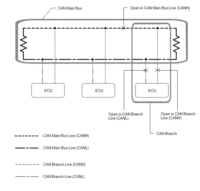
HINT:
- This waveform is measured between terminals CANH and GND, and terminals CANL and GND of the DLC3. (Use this as a reference for diagnosis of CAN communication lines.)
-
When malfunctions in multiple ECUs are suspected based on the CAN bus check and DTCs checked using the Techstream, check the resistance of the CAN bus using an ohmmeter first. If no problems are found, check the following waveforms.
Click here
- If a waveform is not similar to one of the following 3 patterns (Group 1), then an open in a CAN main bus line, an open in a CAN branch line, or a short between a CAN line (CANH or CANL) and ground is suspected (Group 2).
- Wiggle the connector and wire harness to check if the waveform changes.
(a) CAN bus waveforms (Group 1)
(1) Normal waveform
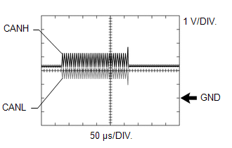
(2) Open in both of the lines (CANH and CANL) of a CAN branch
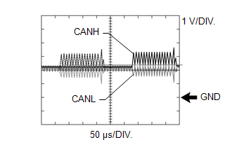
HINT:
- Waveforms (waveforms shown using dotted lines) are not present from an ECU or sensor connected to a CAN branch with an open circuit in both lines. (Waveforms from other ECUs or sensors are normal.)
- Because this waveform is similar to a normal waveform, instead of using the waveform, the malfunctioning part can be narrowed down by performing a CAN bus check.
(3) Short between the CAN bus lines (CANH and CANL)
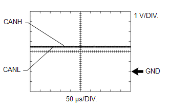
HINT:
- Waveforms disappear.
- If the malfunction is in an ECU, disconnecting the ECU will change the waveform. If the waveform does not change, a malfunction in the wire harness is suspected.
(b) CAN bus waveforms (reference) (Group 2)
NOTICE:
The following CAN bus waveforms can be used only as reference. The actual measured waveform may differ significantly depending on the location of the open or short circuit.
(1) Open in a CAN branch line (CANH)
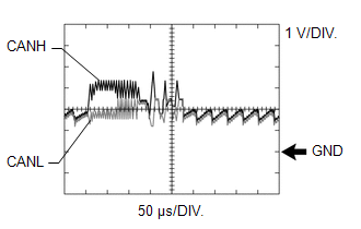
HINT:
- An abnormal waveform is output from an ECU with an open in one of its CAN branch lines. Because this abnormal output interferes with the signals from other ECUs, the output of other ECUs will also appear abnormal.
- Narrow down the malfunctioning part by checking DTCs or performing a CAN bus check, or by checking waveform changes when ECUs or sensors are disconnected. The waveform will change to one for an open in both sides of a CAN branch when the ECU or sensor with an open CAN branch line is disconnected.
(2) Open in a CAN branch line (CANL)
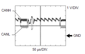
HINT:
- An abnormal waveform is output from an ECU with an open in one of its CAN branch lines. Because this abnormal output interferes with the signals from other ECUs, the output of other ECUs will also appear abnormal.
- Narrow down the malfunctioning part by checking DTCs or performing a CAN bus check, or by checking waveform changes when ECUs or sensors are disconnected. The waveform will change to one for an open in both sides of a CAN branch when the ECU or sensor with an open CAN branch line is disconnected.
(3) Open in a CAN main bus line (CANH)
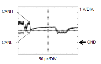
HINT:
- Waveforms of ECUs or sensors that are closer to the DLC3 than the open part are almost normal.
- Waveforms of ECUs or sensors that are on the opposite side of the DLC3 from the open part are abnormal.
- An open in a CAN main bus line can be confirmed by measuring the resistance between the CANH and CANL terminals of any CAN branch.
(4) Short between a CAN bus line (CANH) and ground
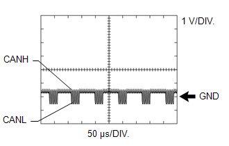
HINT:
- Narrow down the shorted part by checking for waveform changes when disconnecting connectors from the CAN junction connectors or when disconnecting ECUs or sensors.
- A short to ground in the CANH line can be confirmed by measuring the resistance between CANH and ground using an ohmmeter.
(5) Short between a CAN bus line (CANL) and ground
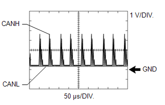
HINT:
- Narrow down the shorted part by checking for waveform changes when disconnecting connectors from the CAN junction connectors or when disconnecting ECUs or sensors.
- A short to ground in the CANL line can be confirmed by measuring the resistance between CANL and ground using an ohmmeter.
DATA SENDING/RECEIVING TABLE
(a) Data sending/receiving table
HINT:
If Data List items related to sent/received data are not displayed properly, the part for which communication is interrupted can be determined using the table below.
| Data Content | Data Detected and Sent by | Data Received by (Can be Checked in the Data List) | Data Received by (Cannot be Checked in the Data List) | Selected System | Relevant Data List Item | Link |
|---|---|---|---|---|---|---|
| Accelerator position | ECM | Skid control ECU (brake actuator assembly) |
| Engine | Accelerator Position | |
| Brake/EPB | Accelerator Opening Angle % | | ||||
| Engine speed | ECM |
|
| Engine | Engine Speed | |
| Brake/EPB | Engine Revolutions | | ||||
| Air suspension | Engine Speed | | ||||
| EMPS | Engine Revolution | | ||||
| Combination Meter | Engine Rpm | | ||||
| Power Source Control | Engine Condition | | ||||
| Head Up Display | Engine Rpm | | ||||
| Engine coolant temperature | ECM |
|
| Engine | Coolant Temp | |
| Combination Meter | Coolant Temperature | | ||||
| Air Conditioner | Engine Coolant Temp | | ||||
| Four Wheel Drive | Engine Coolant Temperature | | ||||
| Vehicle speed | Skid control ECU (brake actuator assembly) |
|
| Brake/EPB | Vehicle Speed | |
| Engine | Vehicle Speed | | ||||
| Navigation System | Vehicle Speed*9 | | ||||
| Vehicle Speed*10 | | |||||
| Radar Cruise2 | Vhcl Spd-Brake ECU | | ||||
| EMPS | Meter Vehicle Velocity | | ||||
| Combination Meter | Vehicle Speed Meter | | ||||
| Head Up Display | Vehicle Speed Meter | | ||||
| Vehicle speed | Combination meter assembly*3 |
|
| Combination Meter | Vehicle Speed Meter | |
| Driver Seat | Vehicle Speed | | ||||
| Power Source Control | Vehicle Speed Signal | | ||||
| Wheel speed | Skid control ECU (brake actuator assembly) |
|
| Brake/EPB | FR Wheel Speed | |
| Air suspension | FL Wheel Speed | | ||||
| AFS*7 | FR Wheel Speed | | ||||
| Four Wheel Drive | FR Wheel Speed | | ||||
| EMPS | Wheel Speed Right | | ||||
| Shift position | ECM |
|
| Engine | Neutral Position SW | |
| Navigation System | Reverse Signal*9 | | ||||
| Reverse Signal*10 | | |||||
| Advanced Parking Guidance/ICS/Intuitive P/A | Parking Signal | | ||||
| Blind Spot Monitor Master | Reverse (Only for AT/CVT) | | ||||
| Driver Seat | P Switch | | ||||
| Power Source Control | Shift P Signal | | ||||
| Ambient temperature | Air conditioning amplifier assembly |
|
| Air Conditioner | Ambient Temp Sensor | |
| Combination Meter | Ambient Temperature | | ||||
| Four Wheel Drive | Ambient Temperature | | ||||
| Driver door courtesy switch | Main body ECU (multiplex network body ECU) | - |
| Main Body | FL Door Courtesy SW | |
| Steering angle | Steering sensor |
|
| Blind Spot Monitor Master | Steering Angle | |
| Brake/EPB | Steering Angle Sensor | | ||||
| Air suspension | Steering Angle | | ||||
| EMPS | Steering Angle Velocity | | ||||
| Four Wheel Drive | Steering Angle Value | | ||||
| Yaw rate |
|
|
| Radar Cruise2 | Yaw Rate Sensor | |
| Blind Spot Monitor Master | Yaw Rate Sensor | | ||||
| Brake/EPB | Yaw Rate Sensor | | ||||
| Four Wheel Drive | Yaw Rate Value | | ||||
| Acceleration |
|
|
| Radar Cruise2 | Vehicle Acceleration | |
| Brake/EPB | Deceleration Sensor | | ||||
| Four Wheel Drive | Forward and Rearward G | | ||||
| Ignition switch condition | Main body ECU (multiplex network body ECU) |
|
| Main Body | IG SW | |
| Tilt&Telescopic | IG Switch | | ||||
| Driver Seat | Ignition Switch | | ||||
| Stop light switch signal | Skid control ECU (brake actuator assembly) |
|
| Brake/EPB | Stop Light SW | |
| Air suspension | Stop Light Switch | | ||||
| Four Wheel Drive | Stop Light SW | | ||||
| Driver side buckle switch signal | Airbag sensor assembly | - |
| SRS Airbag | Left side Buckle SW | |
| Main body ECU (multiplex network body ECU)*4 | - |
| - | - | - | |
| Headlight switch | Main body ECU (multiplex network body ECU) | Headlight ECU sub-assembly LH |
| Main Body | Dimmer SW | |
| Headlight High Beam State | | ||||
| Side turn signal | Combination meter assembly*2 |
|
| Lane Control | Turn Signal Switch (Right) | |
| Blind spot monitor Master | Turn Switch State | | ||||
| Pre-Collision System | Turn Light RH | | ||||
| ECM power source voltage*1 | ECM | - | - | Engine | Battery Voltage | |
| Combination meter assembly power source voltage*1 | Combination meter assembly | - | - | Combination Meter | +B Voltage Value | |
| Skid control ECU (brake actuator assembly) power source voltage*1 | Skid control ECU (brake actuator assembly) | - | - | Brake/EPB | BS1 Voltage Value | |
| Power steering ECU assembly power source voltage*1 | Power steering ECU assembly | - | - | EMPS | IG Power Supply | |
| Radio receiver assembly power source voltage*1 | Radio receiver assembly | - | - | Navigation System | Battery Voltage*9 | |
| Battery Voltage*10 | | |||||
| Absorber control ECU power source voltage*1 | Absorber control ECU | - | - | Air suspension | IG Power Source Voltage | |
| Solar sensor*1 | Air conditioning amplifier assembly | - | - | Air Conditioner | Solar Sensor (D side) | |
| Driver door touch sensor*1 | Certification ECU (smart key ECU assembly) | - | - | Smart Access | D-Door Touch Sensor | |
| Clearance sonar main switch condition*1 | Clearance warning ECU assembly | - | - | Advanced Parking Guidance/ICS/Intuitive P/A | Main Switch | |
| Blind spot monitor sensor LH power source voltage*1 | Blind spot monitor sensor LH | - | - | Blind Spot Monitor Master | Power Supply Voltage | |
| Outer mirror control ECU assembly (for driver side) power source voltage*1 | Outer mirror control ECU assembly (for driver side) | - | - | Mirror L | +B Voltage Input Value | |
| Outer mirror control ECU assembly (for front passenger side) power source voltage*1 | Outer mirror control ECU assembly (for front passenger side) | - | - | Mirror R | +B Voltage Input Value | |
| Position control ECU and switch assembly LH power source voltage*1 | Position control ECU and switch assembly LH | - | - | Driver Seat | Power Voltage | |
| Multiplex tilt and telescopic ECU power source voltage*1 | Multiplex tilt and telescopic ECU | - | - | Tilt&Telescopic | Power Source Voltage | |
| Headlight ECU sub-assembly LH power source voltage*1*8 | Headlight ECU sub-assembly LH | - | - | HL Auto Leveling | +B Voltage Value | |
| Panoramic view monitor main switch condition*1 | Parking assist ECU | - | - | Circumference Monitoring Camera Control Module | Camera Changing SW Signal Status | |
*1: Whether the ECU that sends data is functioning or not can be judged by using the Techstream to check items such as switches or sensors that send signals to the ECU via direct lines.
*2: Although the received contents cannot be checked in the Data List, whether or not the data is received normally can be checked by observing the combination meter assembly.
*3: The combination meter assembly receives a vehicle speed signal from the skid control ECU (brake actuator assembly) and sends the signal to other ECUs.
*4: The main body ECU (multiplex network body ECU) receives a driver seat buckle switch signal from the airbag sensor assembly and sends the signal to other ECUs.
*5: w/ TFT Meter Type Combination Meter Assembly
*6: w/ Optitron Meter Type Combination Meter Assembly
*7: for Multiple Beam Headlight or Single Beam Headlight w/ AFS
*8: for Single Beam Headlight w/o AFS
*9: w/ Navigation System
*10: w/ Audio and Visual System
 Data List / Active Test
DATA LIST / ACTIVE TEST NOTICE: In the table below, the values listed under "Normal Condition" are reference values. Do not depend solely on these reference values when deciding whether a part is faul ...
 Dtc Check / Clear
DTC CHECK / CLEAR CHECK FOR DTC (a) Connect the Techstream to the DLC3. (b) Turn the engine switch on (IG). (c) Turn the Techstream on. (d) Enter the following menus: Body Electrical / Central Gateway ...
Other materials:
Lexus RX (RX 350L, RX450h) 2016-2025 Owners Manual > Rear seats: Folding the third-row seat seatbacks (RX450hL)
■ Before folding the third-row seat seatbacks
1. To prevent the seat belt from
being damaged, hook it to the
seat belt hanger.
2. Lower the third-row seat head restraints to the lowest position.
■ Folding the third-row seat seatbacks
Press and hold the
side of the
switch until the se ...
Lexus RX (RX 350L, RX450h) 2016-2025 Repair Manual > Sfi System: Intake Air Temperature Sensor 1 Bank 1 Circuit Short to Ground (P011011)
DESCRIPTION The intake air temperature sensor, mounted on the mass air flow meter sub-assembly, monitors the intake air temperature. The intake air temperature sensor has a built-in thermistor with a resistance that varies according to the temperature of the intake air. When the intake air temperat ...
Lexus RX (RX 350L, RX450h) 2016-{YEAR} Owners Manual
- For your information
- Pictorial index
- For safety and security
- Instrument cluster
- Operation of each component
- Driving
- Lexus Display Audio system
- Interior features
- Maintenance and care
- When trouble arises
- Vehicle specifications
- For owners
Lexus RX (RX 350L, RX450h) 2016-{YEAR} Repair Manual

0.0168