Lexus RX (RX 350L, RX450h) 2016-2025 Repair Manual: Main Body ECU Communication Stop Mode
DESCRIPTION
| Detection Item | Symptom | Trouble Area |
|---|---|---|
| Main Body ECU Communication Stop Mode | Either condition is met:
|
|
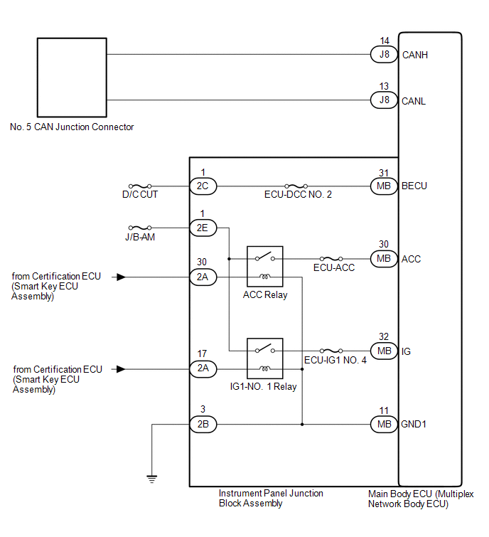
WIRING DIAGRAM
CAUTION / NOTICE / HINT
NOTICE:
- Before measuring the resistance of the CAN bus, turn the engine switch off and leave the vehicle for 1 minute or more without operating the key or any switches, or opening or closing the doors. After that, disconnect the cable from the negative (-) battery terminal and leave the vehicle for 1 minute or more before measuring the resistance.
-
After turning the engine switch off, waiting time may be required before disconnecting the cable from the negative (-) battery terminal. Therefore, make sure to read the disconnecting the cable from the negative (-) battery terminal notices before proceeding with work.
Click here
.gif)
-
Because the order of diagnosis is important to allow correct diagnosis, make sure to begin troubleshooting using How to Proceed with Troubleshooting when CAN communication system related DTCs are output.
Click here
- After performing repairs, perform the DTC check procedure and confirm that the DTCs are not output again.
- DTC check procedure: Turn the engine switch on (IG) and wait for at least 20 seconds. Drive the vehicle at a speed of 5 km/h (3 mph) or more for 7 seconds or more.
-
After the repair, perform the CAN bus check and check that all the ECUs and sensors connected to the CAN communication system are displayed.
Click here
- Inspect the fuses for circuits related to this system before performing the following procedure.
-
If the main body ECU (multiplex network body ECU) is replaced, refer to Registration.
Click here
HINT:
- Operating the engine switch, any other switches or a door triggers related ECU and sensor communication on the CAN. This communication will cause the resistance value to change.
- Even after DTCs are cleared, if a DTC is stored again after driving the vehicle for a while, the malfunction may be occurring due to vibration of the vehicle. In such a case, wiggling the ECUs or wire harness while performing the inspection below may help determine the cause of the malfunction.
PROCEDURE
| 1. | CHECK FOR OPEN IN CAN BUS LINES (MAIN BODY ECU (MULTIPLEX NETWORK BODY ECU) BRANCH LINE) |
(a) Disconnect the cable from the negative (-) battery terminal.
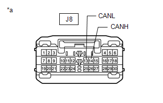
| (b) Disconnect the J8 main body ECU (multiplex network body ECU) connector. |
|
(c) Measure the resistance according to the value(s) in the table below.
Standard Resistance:
| Tester Connection | Condition | Specified Condition |
|---|---|---|
| J8-14 (CANH) - J8-13 (CANL) | Cable disconnected from negative (-) battery terminal | 54 to 69 Ω |
| NG | .gif) | REPAIR OR REPLACE CAN BRANCH LINES OR CONNECTOR (MAIN BODY ECU (MULTIPLEX NETWORK BODY ECU)) |
|
.gif)
| 2. | CHECK HARNESS AND CONNECTOR (POWER SOURCE CIRCUIT) |
(a) Remove the main body ECU (multiplex network body ECU).
Click here
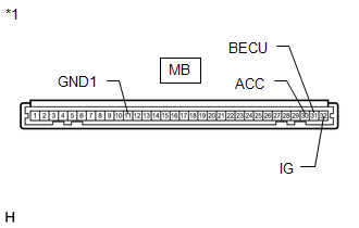
| (b) Measure the resistance according to the value(s) in the table below. Standard Resistance:
|
|
(c) Reconnect the cable to the negative (-) battery terminal.
(d) Measure the voltage according to the value(s) in the table below.
Standard Voltage:
| Tester Connection | Condition | Specified Condition |
|---|---|---|
| MB-30 (ACC) - Body ground | Engine switch on (ACC) | 11 to 14 V |
| MB-31 (BECU) - Body ground | Always | 11 to 14 V |
| MB-32 (IG) - Body ground | Engine switch on (IG) | 11 to 14 V |
| Result | Proceed to |
|---|---|
| OK | A |
| NG (BECU) | B |
| NG (ACC) | C |
| NG (IG) | D |
| NG (GND1) | E |
| A | | REPLACE MAIN BODY ECU (MULTIPLEX NETWORK BODY ECU) |
| C | | GO TO LIGHTING (INT) SYSTEM (ACC SIGNAL CIRCUIT) |
| D | | GO TO LIGHTING (INT) SYSTEM (IG SIGNAL CIRCUIT) |
| E | | GO TO STEP 4 |
|
| 3. | CHECK HARNESS AND CONNECTOR (BECU SIGNAL CIRCUIT) |
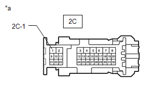
(a) Disconnect the 2C instrument panel junction block assembly connector.
| (b) Measure the voltage according to the value(s) in the table below. Standard Voltage:
|
|
| OK | | REPLACE INSTRUMENT PANEL JUNCTION BLOCK ASSEMBLY |
| NG | | REPAIR OR REPLACE HARNESS OR CONNECTOR (BECU SIGNAL CIRCUIT) |
| 4. | CHECK HARNESS AND CONNECTOR (GROUND CIRCUIT) |
(a) Disconnect the cable from the negative (-) battery terminal.
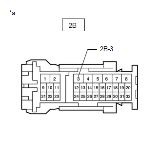
(b) Disconnect the 2B instrument panel junction block assembly connector.
| (c) Measure the resistance according to the value(s) in the table below. Standard Resistance:
|
|
| OK | | REPLACE INSTRUMENT PANEL JUNCTION BLOCK ASSEMBLY |
| NG | | REPAIR OR REPLACE HARNESS OR CONNECTOR (GROUND CIRCUIT) |
 Combination Meter ECU Communication Stop Mode
DESCRIPTION Detection Item Symptom Trouble Area Combination Meter ECU Communication Stop Mode Either condition is met:
"Combination Meter" is not displayed on the CAN Bus Check screen ...
 Suspension Control ECU Communication Stop Mode
DESCRIPTION Detection Item Symptom Trouble Area Suspension Control ECU Communication Stop Mode Either condition is met:
"Suspension Control (Air Suspension)" is not displayed on the CA ...
Other materials:
Lexus RX (RX 350L, RX450h) 2016-2025 Repair Manual > Airbag System: Front Airbag Sensor Lost Communication (RH) (B1612,B1613)
DESCRIPTION The front airbag sensor RH circuit consists of the airbag sensor assembly and front airbag sensor RH. The front airbag sensor RH detects impacts to the vehicle and sends signals to the airbag sensor assembly to determine if the airbags, pretensioners and selectable force limiter should b ...
Lexus RX (RX 350L, RX450h) 2016-2025 Owners Manual > Multi-information display: Using the multi-information display
Using the content display area
The content display area is operated using the meter control switches.
:Select menu icons
:Change
displayed content,
scroll up/down the
screen and move the
cursor
Press: Enter/Set
Press and hold: Reset
Return to the previous scr ...
Lexus RX (RX 350L, RX450h) 2016-{YEAR} Owners Manual
- For your information
- Pictorial index
- For safety and security
- Instrument cluster
- Operation of each component
- Driving
- Lexus Display Audio system
- Interior features
- Maintenance and care
- When trouble arises
- Vehicle specifications
- For owners
Lexus RX (RX 350L, RX450h) 2016-{YEAR} Repair Manual

0.0173