Lexus RX (RX 350L, RX450h) 2016-2025 Repair Manual: Torque Sensor1 (C1511-C1514,C1517)
DESCRIPTION
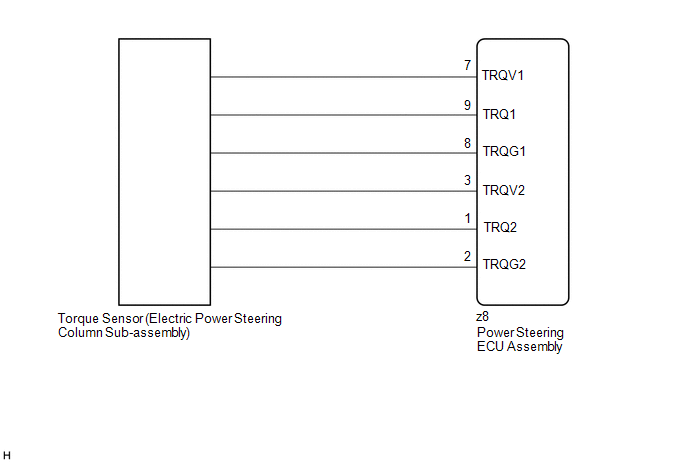
The torque sensor converts the rotational torque received from the steering wheel into electric signals and sends them to the power steering ECU assembly.
| DTC No. | Detection Item | DTC Detection Condition | Trouble Area | Warning Indicate | Return-to-normal Condition | Note |
|---|---|---|---|---|---|---|
| C1511 | Torque Sensor1 | Torque sensor malfunction |
| EPS warning light: Comes on | The ECU judges the system has returned to normal or the power switch is turned on (IG) again | - |
| C1512 | Torque Sensor2 | Torque sensor malfunction |
| EPS warning light: Comes on | The ECU judges the system has returned to normal or the power switch is turned on (IG) again | - |
| C1513 | Torque Sensor Deviation Excessive | Torque sensor malfunction |
| EPS warning light: Comes on | The ECU judges the system has returned to normal or the power switch is turned on (IG) again | - |
| C1514 | Torque Sensor Power Supply Voltage | Torque sensor malfunction |
| EPS warning light: Comes on | Engine switch on (IG) again | - |
| C1517 | Torque Hold | Torque sensor malfunction |
| EPS warning light: Comes on | Engine switch on (IG) again | - |
WIRING DIAGRAM
CAUTION / NOTICE / HINT
NOTICE:
-
If the electric power steering column sub-assembly has been replaced, perform torque sensor zero point calibration.
Click here
.gif)
-
If the power steering ECU assembly has been replaced, perform assist map writing and torque sensor zero point calibration.
Click here
PROCEDURE
| 1. | CHECK CONNECTOR CONNECTION CONDITION |
(a) Check the connection condition of the torque sensor connector.
OK:
Torque sensor connector is securely connected to the power steering ECU assembly.
| NG |  | CONNECT CONNECTOR |
|

| 2. | CHECK POWER STEERING ECU ASSEMBLY (TRQV VOLTAGE) |
| (a) Turn the engine switch to on (IG). |
|
(b) Measure the voltage according to the value(s) in the table below.
Standard Voltage:
| Tester Connection | Condition | Specified Condition |
|---|---|---|
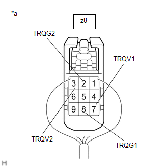
| z8-7 (TRQV1) - z8-8 (TRQG1) | Engine switch on (IG) | 4.5 to 5.5 V |
| z8-3 (TRQV2) - z8-2 (TRQG2) | Engine switch on (IG) | 4.5 to 5.5 V |
| NG | | REPLACE POWER STEERING ECU ASSEMBLY |
|
| 3. | CHECK POWER STEERING ECU ASSEMBLY (TRQ1, TRQ2 VOLTAGE) |
| (a) Start the engine. |
|
(b) Measure the voltage according to the value(s) in the table below.
Standard Voltage:
| Tester Connection | Condition | Specified Condition |
|---|---|---|
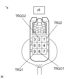
| z8-9 (TRQ1) - z8-8 (TRQG1) | Engine running and steering wheel not being turned (without load) | 2.3 to 2.7 V |
| Engine running and steering wheel being turned to the right with vehicle stopped | 2.5 to 3.8 V | |
| Engine running and steering wheel being turned to the left with vehicle stopped | 1.2 to 2.5 V | |
| z8-1 (TRQ2) - z8-2 (TRQG2) | Engine running and steering wheel not being turned (without load) | 2.3 to 2.7 V |
| Engine running and steering wheel being turned to the right with vehicle stopped | 1.2 to 2.5 V | |
| Engine running and steering wheel being turned to the left with vehicle stopped | 2.5 to 3.8 V |
(c) Under each condition, measure the voltage at terminals TRQ1 and TRQ2, and calculate the sum.
Standard Voltage:
| Tester Connection | Condition | Specified Condition |
|---|---|---|
| Sum of voltage between z8-9 (TRQ1) and z8-8 (TRQG1) and voltage between z8-1 (TRQ2) and z8-2 (TRQG2) | Engine running and steering wheel not being turned (without load) | Between 4.75 V and 5.25 V |
| Engine running and steering wheel being turned to the right with vehicle stopped | ||
| Engine running and steering wheel being turned to the left with vehicle stopped |
| OK | | REPLACE POWER STEERING ECU ASSEMBLY |
| NG | | REPLACE ELECTRIC POWER STEERING COLUMN SUB-ASSEMBLY |

 Torque Sensor Zero Point Adjustment Undone (C1515)
DESCRIPTION This DTC does not indicate a malfunction. The power steering ECU assembly stores this DTC when it determines that torque sensor zero point calibration has not been performed. DTC No. ...
Other materials:
Lexus RX (RX 350L, RX450h) 2016-2025 Repair Manual > Automatic Transaxle Assembly: Installation
INSTALLATION PROCEDURE 1. INSTALL TORQUE CONVERTER ASSEMBLY (a) Turn the front oil pump drive gear so that either key is at the top and place a matchmark on the transaxle housing to indicate the position of the key. *a Matchmark *b Key (b) Place a matchmark on the ...
Lexus RX (RX 350L, RX450h) 2016-2025 Repair Manual > Electrical Key Oscillator (for Front Floor): Installation
INSTALLATION PROCEDURE 1. INSTALL NO. 1 INDOOR ELECTRICAL KEY ANTENNA ASSEMBLY (a) Engage the clamp to install the No. 1 indoor electrical key antenna assembly as shown in the illustration. NOTICE: Be careful when installing the No. 1 indoor electrical key antenna assembly. If the No. 1 indoor elect ...
Lexus RX (RX 350L, RX450h) 2016-{YEAR} Owners Manual
- For your information
- Pictorial index
- For safety and security
- Instrument cluster
- Operation of each component
- Driving
- Lexus Display Audio system
- Interior features
- Maintenance and care
- When trouble arises
- Vehicle specifications
- For owners
Lexus RX (RX 350L, RX450h) 2016-{YEAR} Repair Manual

0.0148