Lexus RX (RX 350L, RX450h) 2016-2025 Repair Manual: Left Low Beam Fan Malfunction (B243D,B243E)
DESCRIPTION
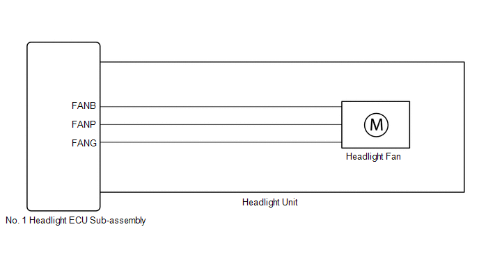
The No. 1 headlight ECU sub-assembly operates the low beam fan to cool the headlight LED unit in order to prevent the headlight LED unit from overheating.
Illuminates the low beam headlights and continuously operates the low beam fan.
The No. 1 headlight ECU sub-assembly monitors the pulse signals from the FANP terminal when the low beam fans are operating.
HINT:
If B243D or B243E is output, the No. 1 headlight ECU sub-assembly performs low beam headlight dimming control.
| DTC No. | Detection Item | DTC Detection Condition | Trouble Area | DTC Output from |
|---|---|---|---|---|
| B243D | Left Low Beam Fan Malfunction |
|
| AFS |
| B243E | Right Low Beam Fan Malfunction |
|
| AFS |
WIRING DIAGRAM
CAUTION / NOTICE / HINT
NOTICE:
-
If the No. 1 headlight ECU sub-assembly LH has been replaced, it is necessary to synchronize the vehicle information and initialize the No. 1 headlight ECU sub-assembly LH.
Click here
.gif)
-
If the headlight assembly LH has been replaced, it is necessary to synchronize the vehicle information and initialize the No. 1 headlight ECU sub-assembly LH.*
Click here
- When replacing the No. 1 headlight ECU sub-assembly LH, always replace it with a new one. If a No. 1 headlight ECU sub-assembly LH which was installed to another vehicle is used, the information stored in it will not match the information from the vehicle and a DTC may be stored.
-
When replacing the headlight assembly LH, always replace it with a new one. If a headlight assembly LH which was installed to another vehicle is used, the information stored in it will not match the information from the vehicle and a DTC may be stored.*
- *: for TMMC Made
PROCEDURE
| 1. | CLEAR DTC |
(a) Connect the Techstream to the DLC3.
(b) Turn the engine switch on (IG).
(c) Turn the Techstream on.
(d) Enter the following menus: Body Electrical / AFS / Trouble Codes.
(e) Clear the DTCs.
Body Electrical > AFS > Clear DTCs
|
.gif)
| 2. | CHECK FOR DTC |
(a) Connect the Techstream to the DLC3.
(b) Turn the engine switch on (IG).
(c) Operate the light control switch to turn on the low beam headlights and wait 120 seconds or more.
(d) Turn the Techstream on.
(e) Enter the following menus: Body Electrical / AFS / Trouble Codes.
(f) Check for DTCs.
Body Electrical > AFS > Trouble CodesOK:
DTC B243D and B243E are not output.
| Result | Proceed to |
|---|---|
| OK | A |
| NG (DTC B243D is output) | B |
| NG (DTC B243E is output) | C |
| A | .gif) | USE SIMULATION METHOD TO CHECK |
| C | | GO TO STEP 6 |
|
| 3. | CHECK HEADLIGHT UNIT LH |
(a) Interchange the headlight unit LH with RH and connect the connectors.
Click here
|
| 4. | CLEAR DTC |
(a) Connect the Techstream to the DLC3.
(b) Turn the engine switch on (IG).
(c) Turn the Techstream on.
(d) Enter the following menus: Body Electrical / AFS / Trouble Codes.
(e) Clear the DTCs.
Body Electrical > AFS > Clear DTCs
|
| 5. | CHECK FOR DTC |
(a) Connect the Techstream to the DLC3.
(b) Turn the engine switch on (IG).
(c) Operate the light control switch to turn on the low beam headlights and wait 120 seconds or more.
(d) Turn the Techstream on.
(e) Enter the following menus: Body Electrical / AFS / Trouble Codes.
(f) Check for DTCs.
Body Electrical > AFS > Trouble Codes| Result | Proceed to |
|---|---|
| DTC B243D is output | A |
| DTC B243E is output (for TMC Made) | B |
| DTC B243E is output (for TMMC Made) | C |
| A | | REPLACE NO. 1 HEADLIGHT ECU SUB-ASSEMBLY LH |
| B | | REPLACE HEADLIGHT UNIT LH |
| C | | REPLACE HEADLIGHT ASSEMBLY LH |
| 6. | CHECK HEADLIGHT UNIT RH |
(a) Interchange the headlight unit RH with LH and connect the connectors.
Click here
|
| 7. | CLEAR DTC |
(a) Connect the Techstream to the DLC3.
(b) Turn the engine switch on (IG).
(c) Turn the Techstream on.
(d) Enter the following menus: Body Electrical / AFS / Trouble Codes.
(e) Clear the DTCs.
Body Electrical > AFS > Clear DTCs
|
| 8. | CHECK FOR DTC |
(a) Connect the Techstream to the DLC3.
(b) Turn the engine switch on (IG).
(c) Operate the light control switch to turn on the low beam headlights and wait 120 seconds or more.
(d) Turn the Techstream on.
(e) Enter the following menus: Body Electrical / AFS / Trouble Codes.
(f) Check for DTCs.
Body Electrical > AFS > Trouble Codes| Result | Proceed to |
|---|---|
| DTC B243E is output | A |
| DTC B243D is output (for TMC Made) | B |
| DTC B243D is output (for TMMC Made) | C |
| A | | REPLACE NO. 1 HEADLIGHT ECU SUB-ASSEMBLY RH |
| B | | REPLACE HEADLIGHT UNIT RH |
| C | | REPLACE HEADLIGHT ASSEMBLY RH |
 Open in IG Circuit (B242E)
DESCRIPTION The No. 1 headlight ECU sub-assembly operates using the power source voltage input from the IG terminal and ECUB terminal. The IG terminal power source voltage is supplied by turning the I ...
 Headlight LH Circuit (B2439,B243A)
DESCRIPTION The No. 1 headlight ECU sub-assembly LH and No. 1 headlight ECU sub-assembly RH internally boost the power supply voltage to ensure a constant supplied current for the lo/hi beam LED of th ...
Other materials:
Lexus RX (RX 350L, RX450h) 2016-2025 Repair Manual > Rear Seat Cushion Heater (for 60/40 Split Seat Type Rh Side): Installation
INSTALLATION CAUTION / NOTICE / HINT CAUTION: Wear protective gloves. Sharp areas on the seat frame may injure your hands. PROCEDURE 1. INSTALL SEAT HEATER ASSEMBLY (w/o Rear No. 2 Seat) (a) Install the seat heater assembly to the separate type rear seat cushion cover with 14 new tag pins. 2. INSTAL ...
Lexus RX (RX 350L, RX450h) 2016-2025 Repair Manual > Power Seat Switch (for Rear No. 2 Seat): Removal
REMOVAL PROCEDURE 1. REMOVE REAR DOOR SCUFF PLATE RH (for Front Side) HINT: Use the same procedure as for the LH side. Click here 2. REMOVE REAR DOOR INSIDE SCUFF PLATE RH (for Front Side) HINT: Use the same procedure as for the LH side. Click here 3. REMOVE REAR SEAT OUTER TRACK BRACKET COVER ...
Lexus RX (RX 350L, RX450h) 2016-{YEAR} Owners Manual
- For your information
- Pictorial index
- For safety and security
- Instrument cluster
- Operation of each component
- Driving
- Lexus Display Audio system
- Interior features
- Maintenance and care
- When trouble arises
- Vehicle specifications
- For owners
Lexus RX (RX 350L, RX450h) 2016-{YEAR} Repair Manual

0.0139