Lexus RX (RX 350L, RX450h) 2016-2025 Repair Manual: Installation
INSTALLATION
CAUTION / NOTICE / HINT
NOTICE:
When replacing the windshield glass of a vehicle equipped with a forward recognition camera, make sure to use a Lexus genuine part. If a non-Lexus genuine part is used, the forward recognition camera may not be able to be installed due to a missing bracket. Also, the dynamic radar cruise control system, lane control system, road sign assist system, pre-collision system, front camera system or automatic high beam system may not operate properly due to a difference in the transmissivity or black ceramic border.
PROCEDURE
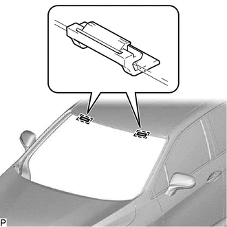
1. INSTALL NO. 1 WINDSHIELD GLASS STOPPER (for 2-piece Type)
| (a) Install 2 new No. 1 windshield glass stoppers to the vehicle body as shown in the illustration. HINT: Only 2-piece type windshield glass stoppers are provided as supply parts. Use 2-piece type stoppers as replacements even if 1-piece type stoppers were originally installed. |
|
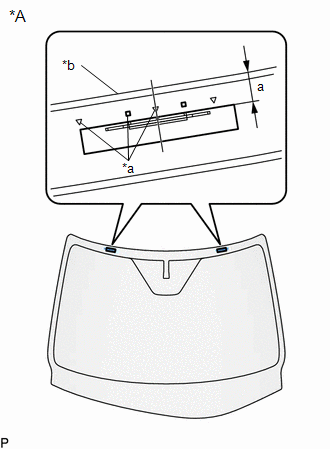
2. INSTALL NO. 2 WINDSHIELD GLASS STOPPER (for 2-piece Type)
(a) Using a brush or sponge, coat the installation area of 2 new No. 2 windshield glass stoppers with primer G.
NOTICE:
- Do not apply too much primer G.
- Allow the primer G to dry for 3 minutes or more.
- Throw away any leftover primer G.
HINT:
If an area other than specified is coated by accident, wipe off the primer G with a clean piece of cloth before it dries.
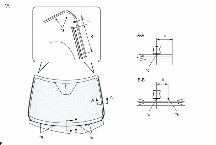
| (b) Install the 2 new No. 2 windshield glass stoppers to the windshield glass as shown in the illustration. Standard Dimension:
HINT: Only 2-piece type windshield glass stoppers are provided as supply parts. Use 2-piece type stoppers as replacements even if 1-piece type stoppers were originally installed. |
|
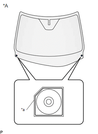
3. INSTALL WINDSHIELD GLASS RETAINER
(a) Using a brush or sponge, coat the installation area of 2 new windshield glass retainers with primer G.
NOTICE:
- Do not apply too much primer G.
- Allow the primer G to dry for 3 minutes or more.
- Throw away any leftover primer G.
HINT:
If an area other than specified is coated by accident, wipe off the primer G with a clean piece of cloth before it dries.
| (b) Install the 2 new windshield glass retainers to the windshield glass as shown in the illustration. |
|
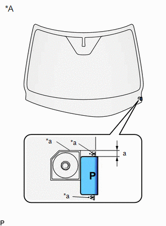
4. INSTALL NO. 2 WINDSHIELD GLASS SPACER
(a) Using a brush or sponge, coat the installation area of a new No. 2 windshield glass spacer with primer G.
NOTICE:
- Do not apply too much primer G.
- Allow the primer G to dry for 3 minutes or more.
- Throw away any leftover primer G.
HINT:
If an area other than specified is coated by accident, wipe off the primer G with a clean piece of cloth before it dries.
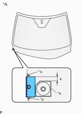
| (b) Install the new No. 2 windshield glass spacer to the windshield glass as shown in the illustration. Standard Dimension:
|
|
5. INSTALL NO. 1 WINDSHIELD GLASS SPACER
(a) Using a brush or sponge, coat the installation area of a new No. 1 windshield glass spacer with primer G.
NOTICE:
- Do not apply too much primer G.
- Allow the primer G to dry for 3 minutes or more.
- Throw away any leftover primer G.
HINT:
If an area other than specified is coated by accident, wipe off the primer G with a clean piece of cloth before it dries.
| (b) Install the new No. 1 windshield glass spacer to the windshield glass as shown in the illustration. Standard Dimension:
|
|
6. INSTALL WINDSHIELD OUTSIDE MOULDING
(a) Using a brush or sponge, coat the installation area of a new windshield outside moulding with primer G.
NOTICE:
- Do not apply too much primer G.
- Allow the primer G to dry for 3 minutes or more.
- Throw away any leftover primer G.
HINT:
If an area other than specified is coated by accident, wipe off the primer G with a clean piece of cloth before it dries.
| (b) Install the new windshield outside moulding to the windshield glass as shown in the illustration. Standard Dimension:
|
|
7. INSTALL WINDSHIELD GLASS SEAL
(a) Using a brush or sponge, coat the installation area of a new windshield glass seal with primer G.
NOTICE:
- Do not apply too much primer G.
- Allow the primer G to dry for 3 minutes or more.
- Throw away any leftover primer G.
HINT:
If an area other than specified is coated by accident, wipe off the primer G with a clean piece of cloth before it dries.
(b) Install the new windshield glass seal to the windshield glass as shown in the illustration.
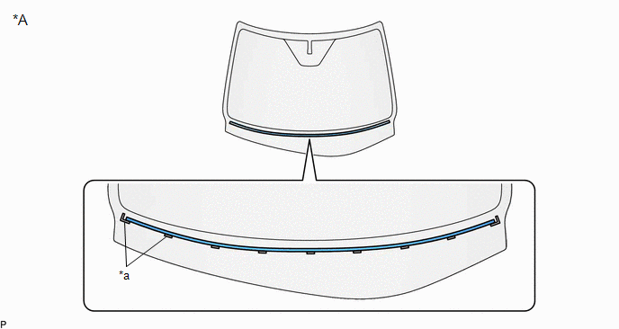
| *A | Back Side | - | - |
| *a | Ceramic Notch | - | - |
8. INSTALL WINDSHIELD GLASS ADHESIVE DAM
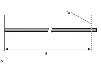
| (a) Cut a new windshield glass adhesive dam so that it is the appropriate size as shown in the illustration. Standard Dimension:
|
|
(b) Using a brush or sponge, coat the installation area of the new windshield glass adhesive dam with primer G.
NOTICE:
- Do not apply too much primer G.
- Allow the primer G to dry for 3 minutes or more.
- Throw away any leftover primer G.
HINT:
If an area other than specified is coated by accident, wipe off the primer G with a clean piece of cloth before it dries.
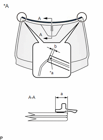
(c) Install the windshield glass adhesive dam to the windshield glass as shown in the illustration.
| *A | Back Side | - | - |
| *a | Ceramic Notch | *b | Adhesive Positioning Center |
| *c | windshield glass adhesive dam Positioning Center | - | - |
.png) | Primer G | - | - |
Standard Dimension:
| Area | Dimension |
|---|---|
| a | 9.5 mm (0.374 in.) |
| b | 6.5 mm (0.256 in.) |
| c | 10.7 mm (0.421 in.) |
| d | 50.0 mm (1.97 in.) |
HINT:
Install the ends of the windshield glass adhesive dam so that they are within the standard dimension (d) shown in the illustration.
9. INSTALL WINDSHIELD GLASS SUB-ASSEMBLY
| (a) Position the windshield glass sub-assembly. (1) Using suction cups, place the windshield glass sub-assembly in the correct position. (2) Check that the whole contact surface of the windshield glass sub-assembly rim is perfectly even. (3) Align the matchmarks on the windshield glass sub-assembly and vehicle body. NOTICE: Check that the windshield glass stoppers are engaged to the vehicle body correctly. (4) Remove the windshield glass sub-assembly. |
|
(b) Using a brush, coat the installation surface on the vehicle body with primer M.
NOTICE:
- Do not coat the adhesive with primer M.
- Do not apply too much primer M.
- Allow the primer M to dry for 3 minutes or more.
- Throw away any leftover primer M.
HINT:
If an area other than specified is coated by accident, wipe off the primer M with a clean piece of cloth before it dries.
(c) Using a brush or sponge, coat the adhesive application area with primer G.
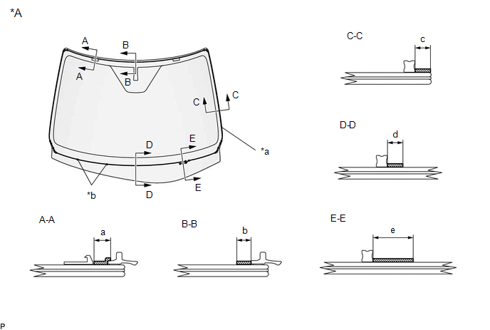
| *A | Back Side | - | - |
| *a | Adhesive Positioning Center | *b | Ceramic Notch |
| | Primer G | - | - |
Standard Dimension:
| Area | Dimension |
|---|---|
| a | 8.0 mm (0.315 in.) |
| b | 11.0 mm (0.433 in.) or more. |
| c | 7.0 mm (0.276 in.) |
| d | 11.0 mm (0.433 in.) or more. |
| e | 19.0 mm (0.748 in.) or more. |
NOTICE:
- Do not apply too much primer G.
- Allow the primer G to dry for 3 minutes or more.
- Throw away any leftover primer G.
HINT:
- Apply primer G to the ceramic notches.
- If an area other than specified is coated by accident, wipe off the primer G with a clean piece of cloth before it dries.
(d) Apply adhesive to the windshield glass sub-assembly.
Adhesive:
Toyota Genuine Windshield Glass Adhesive (High modulus type) or equivalent
| (1) Cut off the tip of the cartridge nozzle as shown in the illustration. Standard Dimension:
|
|
.png)
(2) Load the sealer gun with the cartridge.
(3) Apply adhesive to the windshield glass sub-assembly as shown in the illustration.
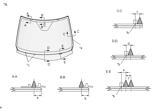
| *A | Back Side | - | - |
| *a | Adhesive Positioning Center | *b | windshield glass adhesive dam Positioning Center |
| *c | Ceramic Notch | - | - |
| | Adhesive | - | - |
Standard Dimension:
| Area | Dimension |
|---|---|
| a | 9.5 mm (0.374 in.) |
| b | 9.5 mm (0.374 in.) |
| c | 6.5 mm (0.256 in.) |
| d | 6.5 mm (0.256 in.) |
| e | 6.5 mm (0.256 in.) |
| f | 8.0 mm (0.315 in.) |
HINT:
Apply adhesive to the ceramic notches.
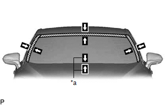
| (e) Install the windshield glass sub-assembly. (1) Using suction cups, position the windshield glass sub-assembly so that the matchmarks are aligned, and press it in gently along the rim. NOTICE:
(2) Lightly press the front surface of the windshield glass sub-assembly to ensure that the windshield glass sub-assembly is securely fit to the vehicle body. HINT: Press the glass with a force of 98 N (10 kgf, 22.0 lbf) or more. (3) Using a scraper, remove any excess or protruding adhesive. (4) Hold the windshield glass sub-assembly using protective tape until the applied adhesive becomes hard. HINT: Follow the instructions supplied by the adhesive manufacturer or in the corresponding instruction manual for the minimum amount of time necessary to wait before driving the vehicle. |
|
(f) w/ Windshield Deicer System:
(1) Connect the connector.
10. INSPECT FOR LEAK
(a) After the adhesive has hardened, apply water from the outside of the vehicle. Check that no water leaks into the cabin.
(b) If water leaks into the cabin, allow the water to dry and add adhesive.
(c) Remove the protective tape.
11. INSTALL ROOF HEADLINING ASSEMBLY
(a) Return the front section of the roof headlining assembly to its original position.
(b) Connect the connector.
12. INSTALL VISOR HOLDER (for LH Side)
Click here .gif)
13. INSTALL VISOR ASSEMBLY LH
Click here
14. INSTALL VISOR BRACKET COVER (for LH Side)
Click here
15. INSTALL ASSIST GRIP ASSEMBLY
w/o Rear No. 2 Seat:
Click here
w/ Rear No. 2 Seat:
Click here
16. INSTALL VISOR HOLDER (for RH Side)
HINT:
Use the same procedure as for the LH side.
17. INSTALL VISOR ASSEMBLY RH
HINT:
Use the same procedure as for the LH side.
18. INSTALL VISOR BRACKET COVER (for RH Side)
HINT:
Use the same procedure as for the LH side.
19. INSTALL FRONT PILLAR GARNISH LH
Click here
20. INSTALL FRONT PILLAR GARNISH RH
HINT:
Use the same procedure as for the LH side.
21. INSTALL MAP LIGHT ASSEMBLY
Click here
22. INSTALL FORWARD RECOGNITION CAMERA
Click here
23. INSTALL RAIN SENSOR (w/ Rain Sensor)
Click here
24. INSTALL INNER REAR VIEW MIRROR ASSEMBLY
Click here
25. INSTALL COWL TOP VENTILATOR LOUVER SUB-ASSEMBLY
Click here
26. INSTALL WINDSHIELD OUTSIDE MOULDING LH
Click here
27. INSTALL WINDSHIELD OUTSIDE MOULDING RH
HINT:
Use the same procedure as for the LH side.
28. INSTALL FRONT WIPER ARM AND BLADE ASSEMBLY RH
Click here
29. INSTALL FRONT WIPER ARM AND BLADE ASSEMBLY LH
Click here
30. INSTALL FRONT WIPER ARM HEAD CAP
Click here
31. INSTALL FRONT FENDER REINFORCEMENT SUB-ASSEMBLY TOP LH
Click here
32. INSTALL FRONT FENDER REINFORCEMENT SUB-ASSEMBLY TOP RH
HINT:
Use the same procedure as for the LH side.
33. INSTALL COOL AIR INTAKE DUCT SEAL
Click here
 Components
COMPONENTS ILLUSTRATION *1 COOL AIR INTAKE DUCT SEAL *2 COWL TOP VENTILATOR LOUVER SUB-ASSEMBLY *3 FRONT FENDER REINFORCEMENT SUB-ASSEMBLY TOP LH *4 FRONT FENDER REINFORCEMENT SUB- ...
 Removal
REMOVAL CAUTION / NOTICE / HINT The necessary procedures (adjustment, calibration, initialization or registration) that must be performed after parts are removed and installed, or replaced during wind ...
Other materials:
Lexus RX (RX 350L, RX450h) 2016-2025 Repair Manual > Automatic Transaxle System: Pressure Control Solenoid "D" Circuit Open (P271313)
DESCRIPTION Refer to DTC P27137F. Click here DTC No. Detection Item DTC Detection Condition Trouble Area MIL Memory Note P271313 Pressure Control Solenoid "D" Circuit Open 1. Diagnosis Condition 2. Malfunction Status 3. Malfunction Time 4. Other
Engine is running
Shif ...
Lexus RX (RX 350L, RX450h) 2016-2025 Repair Manual > Navigation System: Start Up Signal Circuit between Radio Receiver Assembly and Navigation ECU
DESCRIPTION This circuit includes the navigation ECU and radio receiver assembly. WIRING DIAGRAM PROCEDURE 1. CHECK HARNESS AND CONNECTOR (RADIO RECEIVER ASSEMBLY - NAVIGATION ECU) (a) Disconnect the J149 radio receiver assembly connector. (b) Disconnect the J153 navigation ECU connector. ...
Lexus RX (RX 350L, RX450h) 2016-{YEAR} Owners Manual
- For your information
- Pictorial index
- For safety and security
- Instrument cluster
- Operation of each component
- Driving
- Lexus Display Audio system
- Interior features
- Maintenance and care
- When trouble arises
- Vehicle specifications
- For owners
Lexus RX (RX 350L, RX450h) 2016-{YEAR} Repair Manual

0.0209