Lexus RX (RX 350L, RX450h) 2016-2025 Repair Manual: Evaporator Temperature Circuit (B1417/17)
DESCRIPTION
The No. 2 air conditioning harness assembly is installed on the evaporator in the rear air conditioner unit to detect the temperature of the cooled air that has passed through the evaporator, which is used to control the air conditioning system. It sends signals to the air conditioning amplifier assembly. The resistance of the No. 2 air conditioning harness assembly changes in accordance with the temperature of the cooled air that has passed through the evaporator. As the temperature decreases, the resistance increases. As the temperature increases, the resistance decreases.
The air conditioning amplifier assembly applies voltage (5 V) to the No. 2 air conditioning harness assembly and reads voltage changes as the resistance of the No. 2 air conditioning harness assembly changes. This sensor is used for frost prevention.
| DTC No. | Detection Item | DTC Detection Condition | Trouble Area | Memory |
|---|---|---|---|---|
| B1417/17 | Evaporator Temperature Circuit | Open or short in rear evaporator temperature sensor circuit |
| Memorized (4 sec. or more)* |
- *: The air conditioning amplifier assembly stores this DTC if the malfunction has occurred for the period of time indicated in the brackets.
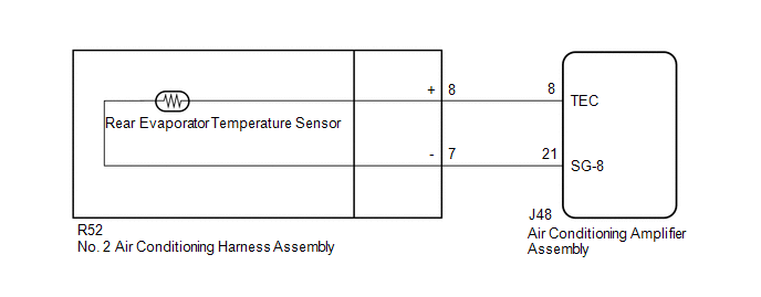
WIRING DIAGRAM
PROCEDURE
| 1. | READ VALUE USING TECHSTREAM |
(a) Connect the Techstream to the DLC3.
(b) Turn the engine switch on (IG).
(c) Turn the Techstream on.
(d) Enter the following menus: Body Electrical / Air Conditioner / Data List.
(e) Check the value(s) by referring to the table below.
Body Electrical > Air Conditioner > Data List| Tester Display | Measurement Item | Range | Normal Condition | Diagnostic Note |
|---|---|---|---|---|
| Evap Temp Sensor (Rear) | No. 2 air conditioning harness assembly | Min.: -29.70°C (-21.46°F) Max.: 59.55°C (139.19°F) | Actual rear evaporator temperature displayed | - |
| Tester Display |
|---|
| Evap Temp Sensor (Rear) |
OK:
The display is as specified in the normal condition column.
| Result | Proceed to |
|---|---|
| OK (When troubleshooting according to Problem Symptoms Table) | A |
| OK (When troubleshooting according to the DTC) | B |
| NG | C |
| A | .gif) | PROCEED TO NEXT SUSPECTED AREA SHOWN IN PROBLEM SYMPTOMS TABLE |
| B | | REPLACE AIR CONDITIONING AMPLIFIER ASSEMBLY |
|
.gif)
| 2. | INSPECT NO. 2 AIR CONDITIONING HARNESS ASSEMBLY |
(a) Remove the No. 2 air conditioning harness assembly.
Click here .gif)
(b) Inspect the No. 2 air conditioning harness assembly.
Click here
| NG | | REPLACE NO. 2 AIR CONDITIONING HARNESS ASSEMBLY |
|
| 3. | CHECK HARNESS AND CONNECTOR (NO. 2 AIR CONDITIONING HARNESS ASSEMBLY - AIR CONDITIONING AMPLIFIER ASSEMBLY) |
(a) Disconnect the J48 air conditioning amplifier assembly connector.
(b) Measure the resistance according to the value(s) in the table below.
Standard Resistance:
| Tester Connection | Condition | Specified Condition |
|---|---|---|
| R52-8 (+) - J48-8 (TEC) | Always | Below 1 Ω |
| R52-7 (-) - J48-21 (SG-8) | Always | Below 1 Ω |
| R52-8 (+) or J48-8 (TEC) - Other terminals and body ground | Always | 10 kΩ or higher |
| R52-7 (-) or J48-21 (SG-8) - Other terminals and body ground | Always | 10 kΩ or higher |
| OK | | REPLACE AIR CONDITIONING AMPLIFIER ASSEMBLY |
| NG | | REPAIR OR REPLACE HARNESS OR CONNECTOR |
 Evaporator Temperature Sensor Circuit (B1413/13)
DESCRIPTION The No. 1 cooler thermistor is installed to the evaporator in the air conditioner unit to detect the temperature of the cooled air that has passed through the evaporator, which is used to ...
 Exhaust Gas Sensor Circuit (B1418/18)
DESCRIPTION The smog ventilation sensor is installed to the front of the cooler condenser assembly to automatically control the air inlet mode (fresh, recirculation/fresh, and recirculation). This sen ...
Other materials:
Lexus RX (RX 350L, RX450h) 2016-2025 Repair Manual > Lighting System (w/o Automatic Headlight Beam Level Control System): Operation Check
OPERATION CHECK AUTOMATIC LIGHT CONTROL SYSTEM OPERATION CHECK NOTICE: Make sure that the customize settings are set to default when performing the automatic light control system operation check. Click here (a) Turn the engine switch on (IG). (b) Turn the light control switch to the AUTO position. ...
Lexus RX (RX 350L, RX450h) 2016-2025 Repair Manual > Fuel Injector (for Port Injection): Removal
REMOVAL CAUTION / NOTICE / HINT The necessary procedures (adjustment, calibration, initialization or registration) that must be performed after parts are removed and installed, or replaced during fuel injector assembly removal/installation are shown below. Necessary Procedures After Parts Removed/In ...
Lexus RX (RX 350L, RX450h) 2016-{YEAR} Owners Manual
- For your information
- Pictorial index
- For safety and security
- Instrument cluster
- Operation of each component
- Driving
- Lexus Display Audio system
- Interior features
- Maintenance and care
- When trouble arises
- Vehicle specifications
- For owners
Lexus RX (RX 350L, RX450h) 2016-{YEAR} Repair Manual

0.0137