Lexus RX (RX 350L, RX450h) 2016-2025 Repair Manual: Removal
REMOVAL
CAUTION / NOTICE / HINT
The necessary procedures (adjustment, calibration, initialization, or registration) that must be performed after parts are removed and installed, or replaced during compressor removal/installation are shown below.
Necessary Procedure After Parts Removed/Installed/Replaced| Replaced Part or Performed Procedure | Necessary Procedure | Effect/Inoperative Function when Necessary Procedure not Performed | Link |
|---|---|---|---|
|
*1: When performing learning using the Techstream.
Click here | |||
| Disconnect cable from negative battery terminal | Memorize steering angle neutral point | Lane Control System | |
| Pre-collision System | |||
| Intelligent Clearance Sonar System*1 | |||
| Parking Assist Monitor System | | ||
| Panoramic View Monitor System | | ||
| Lighting System (w/ Automatic Headlight Beam Level Control System) | | ||
| Initialize back door lock | Power Door Lock Control System | | |
| Reset back door close position | Power Back Door System (w/ Outside Door Control Switch) | | |
| Front television camera view adjustment | Panoramic view monitor system | |
| Front bumper assembly (w/ Intelligent clearance sonar system) |
|
| |
PROCEDURE
1. RECOVER REFRIGERANT FROM REFRIGERATION SYSTEM
Click here .gif)
2. REMOVE V-RIBBED BELT
Click here
3. REMOVE RADIATOR ASSEMBLY
Click here
4. DISCONNECT DISCHARGE HOSE SUB-ASSEMBLY
| (a) Remove the bolt and disconnect the discharge hose sub-assembly from the compressor and magnetic clutch. |
|
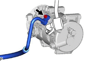
(b) Remove the O-ring from the discharge hose sub-assembly.
NOTICE:
Seal the openings of the disconnected parts using vinyl tape to prevent moisture and foreign matter from entering them.
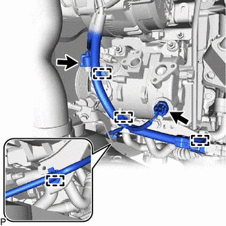
5. DISCONNECT SUCTION HOSE SUB-ASSEMBLY
| (a) Remove the bolt and disconnect the suction hose sub-assembly from the compressor and magnetic clutch. |
|
(b) Remove the O-ring from the suction hose sub-assembly.
NOTICE:
Seal the openings of the disconnected parts using vinyl tape to prevent moisture and foreign matter from entering them.
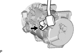
6. REMOVE COMPRESSOR AND MAGNETIC CLUTCH
| (a) Disconnect each connector. |
|
(b) Disengage each clamp.
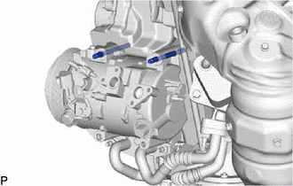
(c) for Type A:
(1) Remove the 2 bolts and 2 nuts, and separate the bracket.
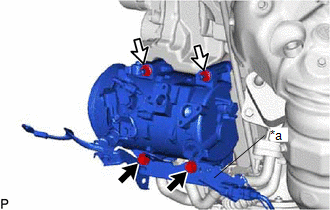
| *a | Bracket |
.png) | Bolt |
.png) | Nut |
| (2) Using an E8 "TORX" socket wrench, remove the 2 stud bolts. |
|
(d) for Type B:
| (1) Remove the 4 bolts and separate the bracket. |
|
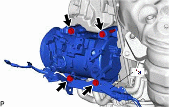
(e) Remove the compressor and magnetic clutch.
 Components
COMPONENTS ILLUSTRATION *A for Type A *B for Type B *1 COMPRESSOR AND MAGNETIC CLUTCH *2 DISCHARGE HOSE SUB-ASSEMBLY *3 SUCTION HOSE SUB-ASSEMBLY *4 O-RING *5 BRACK ...
 Disassembly
DISASSEMBLY PROCEDURE 1. REMOVE COOLER COMPRESSOR BRACKET (a) Disengage the clamp. (b) Remove the screw and cooler compressor bracket. 2. REMOVE MAGNET CLUTCH ASSEMBLY (a) Secure the ...
Other materials:
Lexus RX (RX 350L, RX450h) 2016-2025 Repair Manual > Automatic Transaxle Assembly: Components
COMPONENTS ILLUSTRATION *1 OUTER COWL TOP PANEL SUB-ASSEMBLY - - N*m (kgf*cm, ft.*lbf): Specified torque - - ILLUSTRATION *1 FRONT WHEEL OPENING EXTENSION PAD LH *2 NO. 3 ENGINE UNDER COVER *3 FRONT FENDER APRON SEAL LH - - ILLUSTRATION *1 FRONT L ...
Lexus RX (RX 350L, RX450h) 2016-2025 Repair Manual > Stop Light Switch: On-vehicle Inspection
ON-VEHICLE INSPECTION PROCEDURE 1. INSPECT STOP LIGHT SWITCH ASSEMBLY (a) Disconnect the A55 stop light switch assembly connector. *a Front view of wire harness connector (to Stop Light Switch Assembly) (b) Measure the voltage and resistance on the wire harness side connec ...
Lexus RX (RX 350L, RX450h) 2016-{YEAR} Owners Manual
- For your information
- Pictorial index
- For safety and security
- Instrument cluster
- Operation of each component
- Driving
- Lexus Display Audio system
- Interior features
- Maintenance and care
- When trouble arises
- Vehicle specifications
- For owners
Lexus RX (RX 350L, RX450h) 2016-{YEAR} Repair Manual

0.0153