Lexus RX (RX 350L, RX450h) 2016-2025 Repair Manual: Removal
REMOVAL
CAUTION / NOTICE / HINT
The necessary procedures (adjustment, calibration, initialization or registration) that must be performed after parts are removed and installed, or replaced during roof headlining removal/installation are shown below.
Necessary Procedures After Parts Removed/Installed/Replaced| Replaced Part or Performed Procedure | Necessary Procedure | Effect/Inoperative Function when Necessary Procedure not Performed | Link |
|---|---|---|---|
| Disconnect cable from negative battery terminal | Memorize steering angle neutral point | Lane Control System | |
| Pre-collision System | |||
| Intelligent Clearance Sonar System*1 | |||
| Lighting System (w/ Automatic Headlight Beam Level Control System) | | ||
| Parking Assist Monitor System | | ||
| Panoramic View Monitor System | | ||
| Initialize back door lock | Power Door Lock Control System | | |
| Reset back door close position | Power Back Door System (w/ Outside Door Control Switch) | |
*1: When performing learning using the Techstream.
Click here .gif)
CAUTION:
Some of these service operations affect the SRS airbag system. Read the precautionary notices concerning the SRS airbag system before servicing.
.png)
Click here
PROCEDURE
1. REMOVE TONNEAU COVER ASSEMBLY
(a) Remove the tonneau cover assembly.
2. REMOVE DECK BOARD ASSEMBLY
(a) Remove the deck board assembly.
3. REMOVE REAR NO. 4 FLOOR BOARD
(a) Remove the rear No. 4 floor board.
4. REMOVE DECK SIDE TRIM BOX LH
| (a) Disengage the 2 claws, 2 clips and 4 guides to remove the deck side trim box LH. |
|
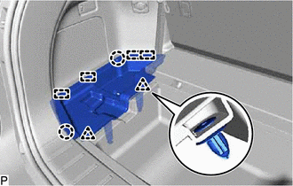
5. REMOVE NO. 1 DECK BOARD
| (a) Disengage the 5 clips to remove the No. 1 deck board. |
|
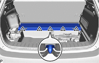
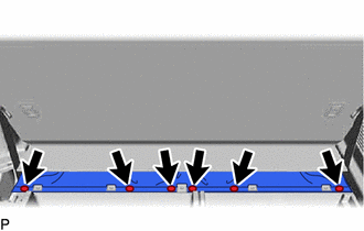
6. DISCONNECT REAR NO. 2 SEAT ASSEMBLY
| (a) Using a clip remover, remove the 6 clips to disconnect the rear No. 2 seat assembly. |
|
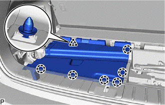
7. REMOVE REAR DECK FLOOR BOX
(a) w/o Woofer:
| (1) Disengage the 6 claws to remove the rear deck floor box. |
|
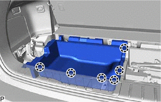
(b) w/ Woofer:
| (1) Disengage the 6 claws and clip to remove the rear deck floor box. |
|
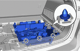
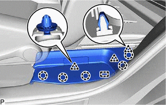
8. REMOVE FRONT DECK FLOOR BOX
| (a) Disengage the 3 claws, clip and 2 guides to remove the front deck floor box. |
|
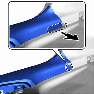
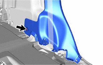
9. REMOVE REAR FLOOR FINISH PLATE
(a) Disengage the claw as shown in the illustration.
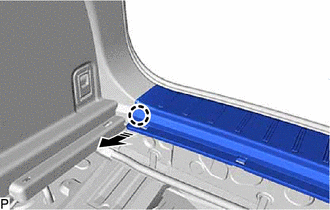
.png) | Remove in this Direction |
HINT:
Use the same procedure for the RH side and LH side.
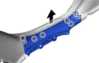
(b) Disengage the 2 claws, 6 clips and 2 guides to remove the rear floor finish plate as shown in the illustration.
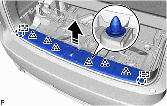
| | Remove in this Direction |
10. REMOVE FRONT DOOR SCUFF PLATE LH
Click here
11. REMOVE FRONT PILLAR GARNISH LH
Click here
12. REMOVE REAR DOOR SCUFF PLATE LH
| (a) Disengage the 5 claws, 3 clips and guide to remove the rear door scuff plate LH. |
|
13. REMOVE REAR DOOR INSIDE SCUFF PLATE LH
(a) Disengage the claw as shown in the illustration.
.png) | Place Hand Here |
| | Remove in this Direction |
HINT:
Use the same procedure for the front side and rear side.
(b) Disengage the 6 claws and 2 guides to remove the rear door inside scuff plate LH as shown in the illustration.
| | Remove in this Direction |
14. REMOVE LOWER CENTER PILLAR GARNISH LH
Click here
15. DISCONNECT FRONT SEAT OUTER BELT ASSEMBLY LH
Click here
16. REMOVE CENTER PILLAR GARNISH ASSEMBLY LH
Click here
17. REMOVE FRONT DOOR SCUFF PLATE RH
HINT:
Use the same procedure as for the LH side.
18. REMOVE FRONT PILLAR GARNISH RH
HINT:
Use the same procedure as for the LH side.
19. REMOVE REAR DOOR SCUFF PLATE RH
HINT:
Use the same procedure as for the LH side.
20. REMOVE REAR DOOR INSIDE SCUFF PLATE RH
HINT:
Use the same procedure as for the LH side.
21. REMOVE LOWER CENTER PILLAR GARNISH RH
HINT:
Use the same procedure as for the LH side.
22. DISCONNECT FRONT SEAT OUTER BELT ASSEMBLY RH
HINT:
Use the same procedure as for the LH side.
23. REMOVE CENTER PILLAR GARNISH ASSEMBLY RH
HINT:
Use the same procedure as for the LH side.
24. REMOVE REAR NO. 1 SEAT ASSEMBLY (for Captain Seat Type)
Click here
25. REMOVE REAR NO. 1 SEAT ASSEMBLY (for 60/40 Split Seat Type LH Side)
Click here
26. REMOVE REAR NO. 1 SEAT ASSEMBLY (for 60/40 Split Seat Type RH Side)
Click here
27. REMOVE REAR NO. 2 SEAT ASSEMBLY
Click here
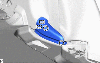
28. REMOVE FRONT DECK SIDE TRIM COVER LH
| (a) Disengage the 2 claws and 2 guides to remove the front deck side trim cover LH. |
|
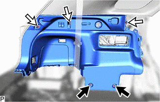
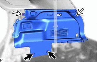
29. REMOVE REAR SEAT SIDE GARNISH LH
| (a) Using a clip remover, remove the clip. |
|
| (b) Disengage the 10 claws and 4 clips to remove the rear seat side garnish LH. |
|
30. REMOVE NO. 1 LUGGAGE COMPARTMENT TRIM HOOK (for LH Side)
Click here
31. REMOVE ROPE HOOK ASSEMBLY (for LH Side)
| (a) Using a screwdriver with its tip wrapped with protective tape, disengage the 2 claws and open the cover. |
|
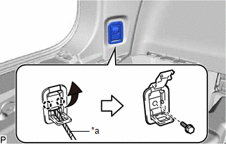
(b) Remove the bolt and rope hook assembly.
32. REMOVE NO. 1 LUGGAGE COMPARTMENT LIGHT ASSEMBLY (for LH Side)
Click here
33. REMOVE NO. 2 AIR CONDITIONING CONTROL ASSEMBLY
Click here
34. REMOVE COOLER (NO. 2 ROOM TEMP. SENSOR) THERMISTOR
Click here
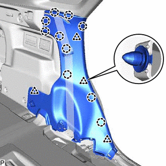
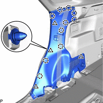
35. REMOVE DECK TRIM SIDE PANEL ASSEMBLY LH
(a) Using a clip remover, remove the 2 clips.
.png) | Clip |
.png) | Bolt |
(b) Remove the 3 bolts.
(c) Disengage the 6 claws and 3 clips.
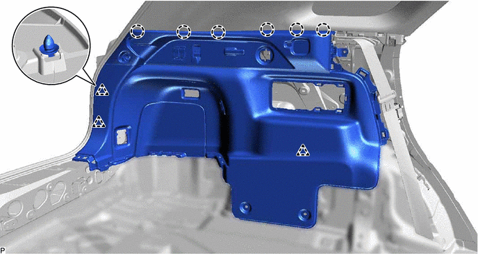
(d) Disconnect each connector to remove the deck trim side panel assembly LH.
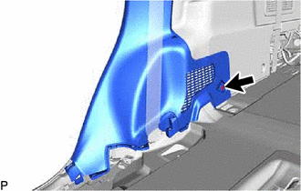
36. DISCONNECT REAR NO. 2 SEAT OUTER BELT ASSEMBLY LH
Click here
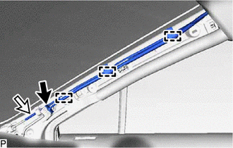
37. REMOVE ROOF SIDE INNER GARNISH ASSEMBLY LH
(a) Disengage the 2 claws and 10 clips to remove the roof side inner garnish assembly LH.
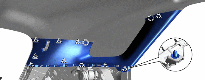
(b) Remove the 10 clips from the roof side inner garnish assembly LH.
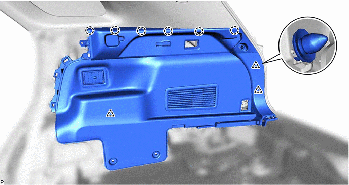
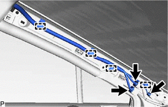
38. REMOVE REAR ROOF SIDE RAIL GARNISH ASSEMBLY LH
| (a) Disengage the 3 clips to remove the rear roof side rail garnish assembly LH. |
|
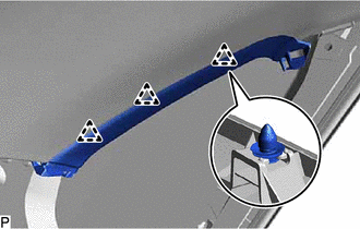
(b) Remove the 3 clips from the rear roof side rail garnish assembly LH.
39. REMOVE FRONT DECK SIDE TRIM COVER RH
HINT:
Use the same procedure as for the LH side.
40. REMOVE REAR SEAT SIDE GARNISH RH
| (a) Using a clip remover, remove the clip. |
|
| (b) Disengage the 10 claws and 4 clips. |
|
(c) Disconnect the connector to remove the rear seat side garnish RH.
41. REMOVE NO. 1 LUGGAGE COMPARTMENT TRIM HOOK (for RH Side)
Click here
42. REMOVE ROPE HOOK ASSEMBLY (for RH Side)
HINT:
Use the same procedure as for the LH side.
43. REMOVE NO. 1 LUGGAGE COMPARTMENT LIGHT ASSEMBLY (for RH Side)
Click here
44. REMOVE DECK TRIM SIDE PANEL ASSEMBLY RH
(a) Using a clip remover, remove the 2 clips.
| | Clip |
| | Bolt |
(b) Remove the 2 bolts.
(c) Disengage the 6 claws and 3 clips to remove the deck trim side panel assembly RH.
45. DISCONNECT REAR NO. 2 SEAT OUTER BELT ASSEMBLY RH
HINT:
Use the same procedure as for the LH side.
46. REMOVE ROOF SIDE INNER GARNISH ASSEMBLY RH
HINT:
Use the same procedure as for the LH side.
47. REMOVE REAR ROOF SIDE RAIL GARNISH ASSEMBLY RH
HINT:
Use the same procedure as for the LH side.
48. REMOVE MAP LIGHT ASSEMBLY
Click here
49. REMOVE SPOT LIGHT ASSEMBLY
Click here
50. REMOVE RAIN SENSOR COVER
Click here
51. REMOVE RAIN SENSOR
Click here
52. REMOVE NO. 2 FORWARD RECOGNITION COVER
Click here
53. REMOVE NO. 1 FORWARD RECOGNITION COVER
Click here
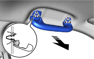
54. REMOVE ASSIST GRIP SUB-ASSEMBLY
HINT:
Use the same procedure for all assist grip sub-assemblies.
| (a) Insert SST into the cutout of the assist grip cover LH as shown in the illustration. SST: 09813-00010 NOTICE: To prevent the assist grip sub-assembly from being damaged, make sure to insert SST straight into the cutout. HINT: Use the same procedure for the LH side and RH side. |
|
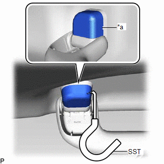
(b) Pull SST as shown in the illustration to disengage the claw.
NOTICE:
To prevent the assist grip sub-assembly from being damaged, make sure to only pull SST as shown in the illustration.

| *a | 30 to 45° |
| | Remove in this Direction |
HINT:
- Use the same procedure for the claw on the other side of the assist grip cover LH.
- Use the same procedure for the LH side and RH side.
(c) Remove the assist grip cover LH.
HINT:
Use the same procedure for the LH side and RH side.
(d) Disengage the 2 clips as shown in the illustration to remove the assist grip sub-assembly.
| | Remove in this Direction |
(e) Remove the 2 clips from the vehicle body.
55. REMOVE REAR ASSIST GRIP ASSEMBLY LH
HINT:
Use the same procedure as for the assist grip sub-assembly.
56. REMOVE REAR ASSIST GRIP ASSEMBLY RH
HINT:
Use the same procedure as for the assist grip sub-assembly.
57. REMOVE VISOR BRACKET COVER LH
HINT:
Use the same procedure as for the visor bracket cover.
Click here
58. REMOVE VISOR ASSEMBLY LH
Click here
59. REMOVE VISOR HOLDER LH
HINT:
Use the same procedure as for the visor holder.
Click here
60. REMOVE VISOR BRACKET COVER RH
HINT:
Use the same procedure as for the LH side.
61. REMOVE VISOR ASSEMBLY RH
HINT:
Use the same procedure as for the LH side.
62. REMOVE VISOR HOLDER RH
HINT:
Use the same procedure as for the LH side.
63. REMOVE ROOF HEADLINING ASSEMBLY
(a) for Windshield Glass Side:
(1) Disconnect each connector.
(b) for Front Pillar LH Side:
(1) Remove the protective cover.
| (2) Disengage the 4 clamps. |
|
(3) Disconnect the 3 connectors.
(4) Install the protective cover.
(c) for Front Pillar RH Side:
(1) Remove the protective cover.
(2) Disengage the 3 clamps.
| | Connector |
| | Washer Hose Assembly |
(3) Disconnect the connector and washer hose assembly.
HINT:
Use a container to collect the windshield washer fluid.
(4) Install the protective cover.
(d) for Rear Pillar RH Side:
(1) Disengage the 2 clamps.
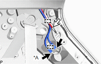
| *A | w/ Satellite Radio |
| | Connector |
| | Washer Hose Assembly |
(2) Disconnect each connector and the washer hose assembly.
HINT:
Use a container to collect the windshield washer fluid.
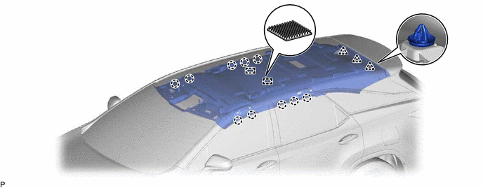
(e) for Standard Roof:
(1) Disengage the 10 claws, 3 clips and 2 fasteners to remove the roof headlining assembly.
(f) for Sliding Roof:
(1) Disconnect the connector.
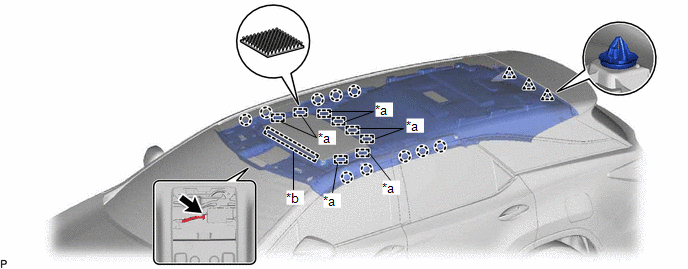
| *a | Fastener | *b | Guide |
(2) Disengage the 10 claws, 3 clips, 8 fasteners and guide to remove the roof headlining assembly.
(g) Remove the roof headlining assembly from the vehicle through the back door as shown in the illustration.
NOTICE:
Do not damage the roof headlining assembly or vehicle interior.

| | Remove in this Direction |
 Reassembly
REASSEMBLY PROCEDURE 1. INSTALL NO. 1 ROOF WIRE (a) When using a new roof headlining assembly: (1) Using a knife, cut the roof headlining assembly at the markings as shown in the illustration. *A ...

Other materials:
Lexus RX (RX 350L, RX450h) 2016-2025 Repair Manual > Road Sign Assist System: Diagnostic Trouble Code Chart
DIAGNOSTIC TROUBLE CODE CHART Road Sign Assist System DTC No. Detection Item Link U010087 Lost Communication with ECM/PCM "A" Missing Message U012587 Lost Communication with Multi-axis Acceleration Sensor Module Missing Message U012987 Lost Communication with Brake ...
Lexus RX (RX 350L, RX450h) 2016-2025 Repair Manual > Center Power Outlet Socket(for Rear No. 1 Seat): Installation
INSTALLATION PROCEDURE 1. INSTALL USB CHARGER SOCKET (a) Engage the 4 claws to install the USB charger socket as shown in the illustration. Install in this Direction 2. INSTALL NO. 2 REAR SEAT CENTER ARMREST BOX Click here 3. INSTALL REAR SEAT CENTER ARMREST DOOR SUB-ASSEMBLY Click here ...
Lexus RX (RX 350L, RX450h) 2016-{YEAR} Owners Manual
- For your information
- Pictorial index
- For safety and security
- Instrument cluster
- Operation of each component
- Driving
- Lexus Display Audio system
- Interior features
- Maintenance and care
- When trouble arises
- Vehicle specifications
- For owners
Lexus RX (RX 350L, RX450h) 2016-{YEAR} Repair Manual

0.013