Lexus RX (RX 350L, RX450h) 2016-2025 Repair Manual: Room Light
Components
COMPONENTS
ILLUSTRATION
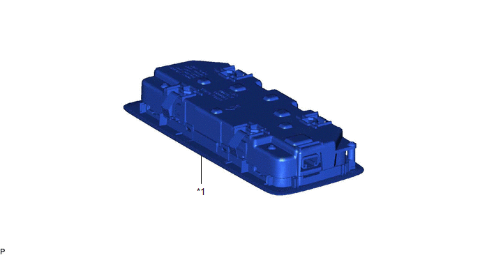
| *1 | SPOT LIGHT ASSEMBLY | - | - |
Inspection
INSPECTION
PROCEDURE
1. INSPECT SPOT LIGHT ASSEMBLY
(a) Inspect the rear dome light.
| (1) Apply battery voltage to the connector and check that the rear map light comes on. OK:
If the result is not as specified, replace the spot light assembly. |
|
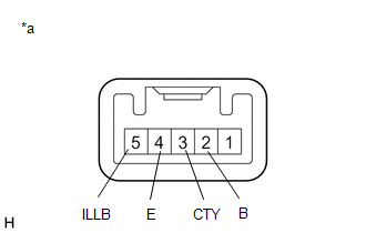
(b) Inspect the switch illumination.
(1) Apply battery voltage to the connector and check that the switch illumination comes on.
OK:
| Measurement Condition | Condition | Specified Condition |
|---|---|---|
| Battery positive (+) → 5 (ILLB) Battery negative (-) → 4 (E) | Always | Switch illumination comes on |
If the result is not as specified, replace the spot light assembly.
Removal
REMOVAL
PROCEDURE
1. REMOVE SPOT LIGHT ASSEMBLY
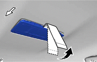
(a) Using the moulding remover D as shown in the illustration, raise the roof headlining assembly until the clip of the spot light assembly can be seen.
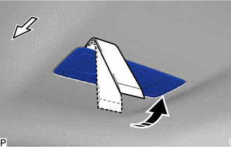
.png) | Front |
.png) | Move in this Direction |
NOTICE:
Be careful not to damage the roof headlining assembly.
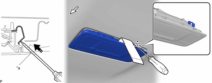
(b) While continuing to hold the moulding remover D, disengage the clip using a screwdriver wrapped with protective tape.
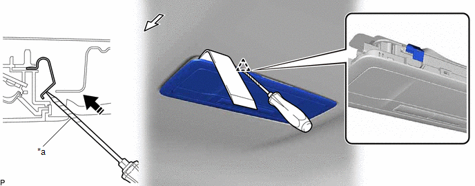
| *a | Protective Tape | - | - |
| | Front | | Push in this Direction |
NOTICE:
Be careful not to damage the roof headlining assembly.
(c) Slide the moulding remover D as shown in the illustration and raise the roof headlining assembly until the clip of the spot light assembly can be seen.
| | Front |
| | Move in this Direction |
NOTICE:
Be careful not to damage the roof headlining assembly.
(d) While continuing to hold the moulding remover D, disengage the clip using a screwdriver wrapped with protective tape.
| *a | Protective Tape | - | - |
| | Front | | Push in this Direction |
NOTICE:
Be careful not to damage the roof headlining assembly.
(e) Disengage the 2 guides.
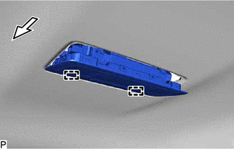
| | Front |
(f) Disconnect the connector to remove the spot light assembly.
Installation
INSTALLATION
PROCEDURE
1. INSTALL SPOT LIGHT ASSEMBLY
(a) Connect the connector.
(b) Engage the 4 clips to install the spot light assembly.
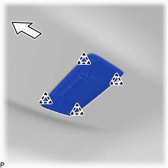
.png) | Front |
 Rear Door Courtesy Switch
ComponentsCOMPONENTS ILLUSTRATION *1 REAR DOOR COURTESY LIGHT SWITCH ASSEMBLY - - N*m (kgf*cm, ft.*lbf): Specified torque - - RemovalREMOVAL CAUTION / NOTICE / HINT HINT:
Us ...
 Scuff Plate Light
ComponentsCOMPONENTS ILLUSTRATION *1 FRONT DOOR SCUFF PLATE LH *2 FRONT DOOR SCUFF PLATE RH RemovalREMOVAL PROCEDURE 1. REMOVE FRONT DOOR SCUFF PLATE LH Click here 2. REMOVE FRONT DO ...
Other materials:
Lexus RX (RX 350L, RX450h) 2016-2025 Repair Manual > Sfi System: Throttle/Pedal Position Sensor/Switch "D" Circuit Short to Battery (P212012,P212014,P21201F,P212512,P212514,P21251F,P21382B)
DESCRIPTION HINT:
This Electronic Throttle Control System (ETCS) does not use a throttle cable.
These DTCs relate to the accelerator pedal position sensor.
The accelerator pedal position sensor is built into the accelerator pedal sensor assembly and has 2 sensor circuits: VPA (main) and VPA2 ...
Lexus RX (RX 350L, RX450h) 2016-2025 Repair Manual > Generator (for 150 A Type): Reassembly
REASSEMBLY PROCEDURE 1. INSTALL GENERATOR DRIVE END FRAME BEARING (a) Using SST and a press, install a new generator drive end frame bearing. SST: 09950-60010 09951-00470 SST: 09950-70010 09951-07100 (b) Fit the tabs of the retainer plate into the cutouts of the generator drive end ...
Lexus RX (RX 350L, RX450h) 2016-{YEAR} Owners Manual
- For your information
- Pictorial index
- For safety and security
- Instrument cluster
- Operation of each component
- Driving
- Lexus Display Audio system
- Interior features
- Maintenance and care
- When trouble arises
- Vehicle specifications
- For owners
Lexus RX (RX 350L, RX450h) 2016-{YEAR} Repair Manual

0.0146