Lexus RX (RX 350L, RX450h) 2016-2025 Repair Manual: Slide Sensor Malfunction (B2650)
DESCRIPTION
When the position control ECU and switch assembly LH does not receive a slide motor position sensor signal despite the seat having been moved forward or backward by power seat motor operation, this DTC is stored.
| DTC No. | Detection Item | DTC Detection Condition | Trouble Area |
|---|---|---|---|
| B2650 | Slide Sensor Malfunction | The forward and backward lock detection position of slide motor position sensor is the same. |
|
WIRING DIAGRAM
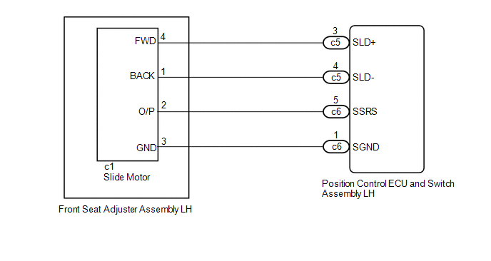
PROCEDURE
| 1. | CLEAR DTC |
(a) Clear the DTCs.
Click here .gif)
|
.gif)
| 2. | CHECK FOR DTC |
(a) Check for DTCs.
Click here
OK:
DTC B2650 is not output.
| OK | .gif) | USE SIMULATION METHOD TO CHECK |
|
| 3. | PERFORM ACTIVE TEST USING TECHSTREAM (SLIDE MOTOR) |
(a) Connect the Techstream to the DLC3.
(b) Turn the engine switch on (IG).
(c) Turn the Techstream on.
(d) Enter the following menus: Body Electrical / Driver Seat / Active Test.
(e) Perform the Active Test according to the display on the Techstream.
Body Electrical > Driver Seat > Active Test| Tester Display | Measurement Item | Control Range | Diagnostic Note |
|---|---|---|---|
| Seat Slide Operation | Seat slide operation | OFF/Rear/Front | - |
| Tester Display |
|---|
| Seat Slide Operation |
OK:
Motor operates normally.
| NG | | GO TO STEP 7 |
|
| 4. | CHECK POSITION CONTROL ECU AND SWITCH ASSEMBLY LH (SLIDE MOTOR CIRCUIT) |
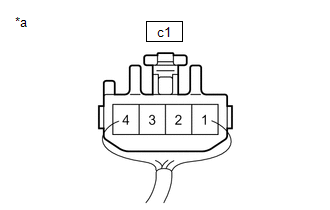
(a) Disconnect the c1 slide motor (front seat adjuster assembly LH) connector.
(b) Measure the voltage according to the value(s) in the table below.
Standard Voltage:
| Tester Connection | Condition | Specified Condition |
|---|---|---|
| c1-2 (O/P) - c1-3 (GND) | Slide switch on | 4.8 to 5.1 V |
| NG | | GO TO STEP 6 |
|
| 5. | CHECK SLIDE MOTOR (FRONT SEAT ADJUSTER ASSEMBLY LH) |
| (a) Reconnect the c1 slide motor (front seat adjuster assembly LH) connector. |
|
(b) Measure the voltage according to the value(s) in the table below.
Standard Voltage:
| Tester Connection | Condition | Specified Condition |
|---|---|---|
| c1-2 (O/P) - Body ground | Slide motor operating | 4.5 to 4.8 V |
| OK | | REPLACE POSITION CONTROL ECU AND SWITCH ASSEMBLY LH |
| NG | | REPLACE SLIDE MOTOR (FRONT SEAT ADJUSTER ASSEMBLY LH) |
| 6. | CHECK HARNESS AND CONNECTOR (POSITION CONTROL ECU AND SWITCH ASSEMBLY LH - SLIDE MOTOR (FRONT SEAT ADJUSTER ASSEMBLY LH)) |
(a) Disconnect the c6 position control ECU and switch assembly LH connector.
(b) Measure the resistance according to the value(s) in the table below.
Standard Resistance:
| Tester Connection | Condition | Specified Condition |
|---|---|---|
| c6-5 (SSRS) - c1-2 (O/P) | Always | Below 1 Ω |
| c6-5 (SSRS) or c1-2 (O/P) - Body ground | Always | 10 kΩ or higher |
| c6-1 (SGND) - c1-3 (GND) | Always | Below 1 Ω |
| c6-1 (SGND) or c1-3 (GND) - Body ground | Always | 10 kΩ or higher |
| OK | | REPLACE POSITION CONTROL ECU AND SWITCH ASSEMBLY LH |
| NG | | REPAIR OR REPLACE HARNESS OR CONNECTOR |
| 7. | INSPECT SLIDE MOTOR (FRONT SEAT ADJUSTER ASSEMBLY LH) |
(a) Remove the front seat adjuster assembly LH.
Click here
(b) Inspect the front seat adjuster assembly LH (slide motor).
Click here
| NG | | REPLACE SLIDE MOTOR (FRONT SEAT ADJUSTER ASSEMBLY LH) |
|
| 8. | CHECK HARNESS AND CONNECTOR (POSITION CONTROL ECU AND SWITCH ASSEMBLY LH - SLIDE MOTOR (FRONT SEAT ADJUSTER ASSEMBLY LH)) |
(a) Disconnect the c5 position control ECU and switch assembly LH connector.
(b) Measure the resistance according to the value(s) in the table below.
Standard Resistance:
| Tester Connection | Condition | Specified Condition |
|---|---|---|
| c5-3 (SLD+) - c1-4 (FWD) | Always | Below 1 Ω |
| c5-3 (SLD+) or c1-4 (FWD) - Body ground | Always | 10 kΩ or higher |
| c5-4 (SLD-) - c1-1 (BACK) | Always | Below 1 Ω |
| c5-4 (SLD-) or c1-1 (BACK) - Body ground | Always | 10 kΩ or higher |
| OK | | REPLACE POSITION CONTROL ECU AND SWITCH ASSEMBLY LH |
| NG | | REPAIR OR REPLACE HARNESS OR CONNECTOR |
 Diagnostic Trouble Code Chart
DIAGNOSTIC TROUBLE CODE CHART Front Power Seat Control System (w/ Memory) DTC No. Detection Item Link B2650 Slide Sensor Malfunction B2658 Short in Sensor with Motor Power Supp ...
 Short in Sensor with Motor Power Supply Circuit (B2658)
DESCRIPTION This DTC is stored when the slide motor is being operated (the slide motor position sensor is being supplied with power) and the power supply voltage does not rise to the specified value. ...
Other materials:
Lexus RX (RX 350L, RX450h) 2016-2025 Repair Manual > Transfer Assembly: Disassembly
DISASSEMBLY CAUTION / NOTICE / HINT NOTICE: Before installation of each part, thoroughly clean and dry it. Then apply grease or oil as necessary. Do not use alkaline chemicals to clean aluminum parts, rubber parts or precoated bolts. Also, do not use non-residue solvent or other cleaning oils to cle ...
Lexus RX (RX 350L, RX450h) 2016-2025 Repair Manual > Power Seat Switch(for Rear Side): Installation
INSTALLATION PROCEDURE 1. INSTALL FOLD SEAT SWITCH ASSEMBLY (for Luggage Compartment) (a) Connect the connector. (b) Engage the 4 claws to install the fold seat switch assembly. 2. INSTALL REAR POWER SEAT SWITCH RH (for 60/40 Split Seat Type RH Side) (a) Engage the 2 claws to install ...
Lexus RX (RX 350L, RX450h) 2016-{YEAR} Owners Manual
- For your information
- Pictorial index
- For safety and security
- Instrument cluster
- Operation of each component
- Driving
- Lexus Display Audio system
- Interior features
- Maintenance and care
- When trouble arises
- Vehicle specifications
- For owners
Lexus RX (RX 350L, RX450h) 2016-{YEAR} Repair Manual

0.0147