Lexus RX (RX 350L, RX450h) 2016-2025 Repair Manual: Inspection
INSPECTION
PROCEDURE
1. INSPECT SPIRAL CABLE SUB-ASSEMBLY
NOTICE:
- Do not remove the steering sensor from the spiral cable sub-assembly when inspecting the spiral cable sub-assembly.
- Remove the steering sensor from the spiral cable sub-assembly only when replacing the spiral cable sub-assembly.
(a) Visually check the spiral cable sub-assembly for defects.
(1) The defects are as follows:
- Scratches
- Small cracks
- Dents
- Chips
-
Cracks or other damage to the connector
OK:
No defects are found.
If any of the defects is found, replace the spiral cable sub-assembly with a new one.
(b) Check the spiral cable sub-assembly.
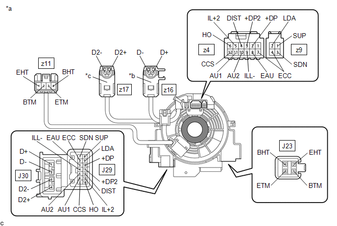
| *a | Component without harness connected (Spiral Cable Sub-assembly) | *b | Color: Light Green |
| *c | Color: Black | - | - |
.png) | Interlock | - | - |
NOTICE:
- When rotating the spiral cable sub-assembly, make sure to push on the interlock shown in the illustration to release the interlock mechanism.
- As the spiral cable sub-assembly may break, do not rotate the spiral cable sub-assembly more than the specified amount.
(1) Set the spiral cable sub-assembly to the center position.
Click here .gif)
(2) Measure the resistance between each terminal of the spiral cable sub-assembly according to the value(s) in the table below.
Standard Resistance:
| Tester Connection | Condition | Specified Condition |
|---|---|---|
| J29-1 (SDN) - z9-3 (SDN) | Always | 3 Ω or less |
| J29-2 (ECC) - z4-7 (ECC) | Always | 3 Ω or less |
| J29-2 (ECC) - z9-4 (ECC) | Always | 3 Ω or less |
| J29-3 (EAU) - z4-8 (EAU) | Always | 3 Ω or less |
| J29-4 (ILL-) - z4-9 (ILL-) | Always | 3 Ω or less |
| J29-5 (AU2) - z4-10 (AU2) | Always | 3 Ω or less |
| J29-6 (AU1) - z4-11 (AU1) | Always | 3 Ω or less |
| J29-7 (CCS) - z4-12 (CCS) | Always | 3 Ω or less |
| J29-8 (SUP) - z9-1 (SUP) | Always | 3 Ω or less |
| J29-9 (LDA) - z9-2 (LDA) | Always | 3 Ω or less |
| J29-10 (+DP) - z4-2 (+DP) | Always | 3 Ω or less |
| J29-11 (+DP2) - z4-3 (+DP2) | Always | 3 Ω or less |
| J29-12 (DIST) - z4-4 (DIST) | Always | 3 Ω or less |
| J29-13 (IL+2) - z4-5 (IL+2) | Always | 3 Ω or less |
| J29-14 (HO) - z4-6 (HO) | Always | 3 Ω or less |
| J30-1 (D+) - z16-2 (D+) | Always | Below 1 Ω |
| J30-2 (D-) - z16-1 (D-) | Always | Below 1 Ω |
| J30-3 (D2-) - z17-1 (D2-) | Always | Below 1 Ω |
| J30-4 (D2+) - z17-2 (D2+) | Always | Below 1 Ω |
| J23-1 (BTM) - z11-2 (BTM) | Always | 3 Ω or less |
| J23-2 (EHT) - z11-1 (EHT) | Always | Below 0.1 Ω |
| J23-3 (ETM) - z11-3 (ETM) | Always | 3 Ω or less |
| J23-4 (BHT) - z11-4 (BHT) | Always | Below 0.1 Ω |
(3) After setting the spiral cable sub-assembly to the center position, rotate the spiral cable sub-assembly 2.5 times clockwise, and measure the resistance according to the value(s) in the table below. Then rotate the spiral cable sub-assembly 5 times counterclockwise, and measure the resistance according to the value(s) in the table below.
Standard Resistance:
| Tester Connection | Condition | Specified Condition |
|---|---|---|
| J29-1 (SDN) - z9-3 (SDN) | Always | 3 Ω or less |
| J29-2 (ECC) - z4-7 (ECC) | Always | 3 Ω or less |
| J29-2 (ECC) - z9-4 (ECC) | Always | 3 Ω or less |
| J29-3 (EAU) - z4-8 (EAU) | Always | 3 Ω or less |
| J29-4 (ILL-) - z4-9 (ILL-) | Always | 3 Ω or less |
| J29-5 (AU2) - z4-10 (AU2) | Always | 3 Ω or less |
| J29-6 (AU1) - z4-11 (AU1) | Always | 3 Ω or less |
| J29-7 (CCS) - z4-12 (CCS) | Always | 3 Ω or less |
| J29-8 (SUP) - z9-1 (SUP) | Always | 3 Ω or less |
| J29-9 (LDA) - z9-2 (LDA) | Always | 3 Ω or less |
| J29-10 (+DP) - z4-2 (+DP) | Always | 3 Ω or less |
| J29-11 (+DP2) - z4-3 (+DP2) | Always | 3 Ω or less |
| J29-12 (DIST) - z4-4 (DIST) | Always | 3 Ω or less |
| J29-13 (IL+2) - z4-5 (IL+2) | Always | 3 Ω or less |
| J29-14 (HO) - z4-6 (HO) | Always | 3 Ω or less |
| J30-1 (D+) - z16-2 (D+) | Always | Below 1 Ω |
| J30-2 (D-) - z16-1 (D-) | Always | Below 1 Ω |
| J30-3 (D2-) - z17-1 (D2-) | Always | Below 1 Ω |
| J30-4 (D2+) - z17-2 (D2+) | Always | Below 1 Ω |
| J23-1 (BTM) - z11-2 (BTM) | Always | 3 Ω or less |
| J23-2 (EHT) - z11-1 (EHT) | Always | Below 0.1 Ω |
| J23-3 (ETM) - z11-3 (ETM) | Always | 3 Ω or less |
| J23-4 (BHT) - z11-4 (BHT) | Always | Below 0.1 Ω |
(4) After setting the spiral cable sub-assembly to the center position, rotate the spiral cable sub-assembly 2.5 times clockwise. Then while rotating the spiral cable sub-assembly 5 times counterclockwise, measure the resistance according to the value(s) in the table below.
Standard Resistance:
| Tester Connection | Condition | Specified Condition |
|---|---|---|
| J29-1 (SDN) - z9-3 (SDN) | Always | 3 Ω or less |
| J29-2 (ECC) - z4-7 (ECC) | Always | 3 Ω or less |
| J29-2 (ECC) - z9-4 (ECC) | Always | 3 Ω or less |
| J29-3 (EAU) - z4-8 (EAU) | Always | 3 Ω or less |
| J29-4 (ILL-) - z4-9 (ILL-) | Always | 3 Ω or less |
| J29-5 (AU2) - z4-10 (AU2) | Always | 3 Ω or less |
| J29-6 (AU1) - z4-11 (AU1) | Always | 3 Ω or less |
| J29-7 (CCS) - z4-12 (CCS) | Always | 3 Ω or less |
| J29-8 (SUP) - z9-1 (SUP) | Always | 3 Ω or less |
| J29-9 (LDA) - z9-2 (LDA) | Always | 3 Ω or less |
| J29-10 (+DP) - z4-2 (+DP) | Always | 3 Ω or less |
| J29-11 (+DP2) - z4-3 (+DP2) | Always | 3 Ω or less |
| J29-12 (DIST) - z4-4 (DIST) | Always | 3 Ω or less |
| J29-13 (IL+2) - z4-5 (IL+2) | Always | 3 Ω or less |
| J29-14 (HO) - z4-6 (HO) | Always | 3 Ω or less |
| J30-1 (D+) - z16-2 (D+) | Always | Below 1 Ω |
| J30-2 (D-) - z16-1 (D-) | Always | Below 1 Ω |
| J30-3 (D2-) - z17-1 (D2-) | Always | Below 1 Ω |
| J30-4 (D2+) - z17-2 (D2+) | Always | Below 1 Ω |
| J23-1 (BTM) - z11-2 (BTM) | Always | 3 Ω or less |
| J23-2 (EHT) - z11-1 (EHT) | Always | Below 0.1 Ω |
| J23-3 (ETM) - z11-3 (ETM) | Always | 3 Ω or less |
| J23-4 (BHT) - z11-4 (BHT) | Always | Below 0.1 Ω |
If the result is not as specified, replace the spiral cable sub-assembly.
 Removal
REMOVAL CAUTION / NOTICE / HINT The necessary procedures (adjustment, calibration, initialization, or registration) that must be performed after parts are removed, installed, or replaced during the sp ...
 Installation
INSTALLATION PROCEDURE 1. INSPECT SPIRAL CABLE SUB-ASSEMBLY NOTICE: If the steering sensor is installed to a misaligned spiral cable sub-assembly, DTCs for an abnormal steering sensor value such as DT ...
Other materials:
Lexus RX (RX 350L, RX450h) 2016-2025 Repair Manual > Charging System: Data List / Active Test
DATA LIST / ACTIVE TEST DATA LIST HINT: Using the Techstream to read the Data List allows the values or states of switches, sensors, actuators and other items to be read without removing any parts. This non-intrusive inspection can be very useful because intermittent conditions or signals may be dis ...
Lexus RX (RX 350L, RX450h) 2016-2025 Repair Manual > Washer Nozzle(for Front Side): Removal
REMOVAL CAUTION / NOTICE / HINT HINT:
Use the same procedure for the RH side and LH side.
The following procedure is for the LH side.
PROCEDURE 1. REMOVE WASHER NOZZLE SUB-ASSEMBLY (a) Using a screwdriver, disengage the 2 claws as indicated by the arrows, in the order shown in the illustrati ...
Lexus RX (RX 350L, RX450h) 2016-{YEAR} Owners Manual
- For your information
- Pictorial index
- For safety and security
- Instrument cluster
- Operation of each component
- Driving
- Lexus Display Audio system
- Interior features
- Maintenance and care
- When trouble arises
- Vehicle specifications
- For owners
Lexus RX (RX 350L, RX450h) 2016-{YEAR} Repair Manual

0.0144