Lexus RX (RX 350L, RX450h) 2016-2025 Repair Manual: Security Indicator Light Does not Blink
DESCRIPTION
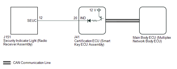
- The certification ECU (smart key ECU assembly) blinks the security indicator light (radio receiver assembly) when the immobiliser is set (engine switch off).
- The certification ECU (smart key ECU assembly) receives the security indicator light signal from the main body ECU (multiplex network body ECU) via CAN communication when the theft deterrent system is in the arming preparation state or alarm sounding state. Then, the certification ECU (smart key ECU assembly) blinks the security indicator light (radio receiver assembly).
WIRING DIAGRAM
CAUTION / NOTICE / HINT
NOTICE:
- When using the Techstream with the engine switch off, connect the Techstream to the DLC3 and turn a courtesy light switch on and off at intervals of 1.5 seconds or less until communication between the Techstream and the vehicle begins. Then select the vehicle type under manual mode and enter the following menus: Body Electrical / Smart Access. While using the Techstream, periodically turn a courtesy light switch on and off at intervals of 1.5 seconds or less to maintain communication between the Techstream and the vehicle.
-
Before replacing the certification ECU (smart key ECU assembly) or main body ECU (multiplex network body ECU), refer to Registration.
Click here
.gif)
PROCEDURE
| 1. | CHECK FOR DTC |
(a) Check for DTCs.
Body Electrical > Smart Access > Trouble Codes Powertrain > Engine > Trouble CodesOK:
DTCs are not output.
| NG | .gif) | GO TO DIAGNOSTIC TROUBLE CODE CHART |
|
.gif)
| 2. | PERFORM ACTIVE TEST USING TECHSTREAM (IMMOBILISER INDICATOR) |
(a) Connect the Techstream to the DLC3.
(b) Turn the engine switch on (IG).
(c) Turn the Techstream on.
(d) Enter the following menus: Body Electrical / Smart Access / Active Test.
(e) Perform the Active Test according to the display on the Techstream.
Body Electrical > Smart Access > Active Test| Tester Display | Measurement Item | Control Range | Diagnostic Note |
|---|---|---|---|
| Immobiliser Indicator | Security indicator light | OFF/ON | - |
| Tester Display |
|---|
| Immobiliser Indicator |
OK:
The security indicator light (radio receiver assembly) operates normally.
| NG | | GO TO STEP 4 |
|
| 3. | CHECK SECURITY INDICATOR LIGHT (RADIO RECEIVER ASSEMBLY) OPERATION |
(a) When the immobiliser is set, check that the security indicator light (radio receiver assembly) blinks.*1
OK:
The security indicator light (radio receiver assembly) blinks normally.
(b) When the theft deterrent system is in the arming preparation state, check that the security indicator light (radio receiver assembly) illuminates.*2
OK:
The security indicator light (radio receiver assembly) illuminates normally.
| Result | Proceed to |
|---|---|
| *1 is NG (*2 is OK) | A |
| *2 is NG (*1 is OK) | B |
| A | | REPLACE CERTIFICATION ECU (SMART KEY ECU ASSEMBLY) |
| B | | REPLACE MAIN BODY ECU (MULTIPLEX NETWORK BODY ECU) |
| 4. | CHECK HARNESS AND CONNECTOR (CERTIFICATION ECU (SMART KEY ECU ASSEMBLY) - SECURITY INDICATOR LIGHT (RADIO RECEIVER ASSEMBLY)) |
(a) Disconnect the J41 certification ECU (smart key ECU assembly) connector.
(b) Disconnect the J151 security indicator light (radio receiver assembly) connector.
(c) Measure the resistance according to the value(s) in the table below.
Standard Resistance:
| Tester Connection | Condition | Specified Condition |
|---|---|---|
| J41-20 (IND) - J151-12 (SEUC) | Always | Below 1 Ω |
| J41-20 (IND) or J151-12 (SEUC) - Body ground | Always | 10 kΩ or higher |
| NG | | REPAIR OR REPLACE HARNESS OR CONNECTOR |
|
| 5. | CHECK CERTIFICATION ECU (SMART KEY ECU ASSEMBLY) |
(a) Reconnect the J41 certification ECU (smart key ECU assembly) connector.
(b) Reconnect the J151 security indicator light (radio receiver assembly) connector.
(c) Using an oscilloscope, check the waveform.
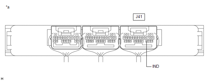
| *a | Component with harness connected (Certification ECU (Smart Key ECU Assembly)) | - | - |
Measurement Condition:
| Tester Connection | Condition | Specified Condition |
|---|---|---|
| J41-20 (IND) - Body ground | Engine switch off → on (IG) | Pulse generation → Below 2 V |
| OK | | REPLACE SECURITY INDICATOR LIGHT (RADIO RECEIVER ASSEMBLY) |
| NG | | REPLACE CERTIFICATION ECU (SMART KEY ECU ASSEMBLY) |
 Engine Immobiliser System Incorrect Assembly (B279C95)
DESCRIPTION If an ECM that is incompatible with the immobiliser system is installed, the ECM will store this DTC. DTC No. Detection Item DTC Detection Condition Trouble Area Note B279C9 ...
 Immobiliser System does not Operate Properly
DESCRIPTION The immobiliser system compares the ID code that is registered to the certification ECU (smart key ECU assembly) with the ID code of the transponder chip that is embedded in the electrical ...
Other materials:
Lexus RX (RX 350L, RX450h) 2016-2025 Repair Manual > Can Communication System: Lost Communication with Gateway Module (Main Body ECU) (U1002)
DESCRIPTION
The main body ECU (multiplex network body ECU) will store this DTC when no signals can be received from the ECUs that have been memorized as those that are connected to sub bus 1.
When the main body ECU (multiplex network body ECU) receives a response signal from the ECUs connected ...
Lexus RX (RX 350L, RX450h) 2016-2025 Repair Manual > Audio / Video: Window Glass Antenna Wire
On-vehicle InspectionON-VEHICLE INSPECTION PROCEDURE 1. INSPECT WINDOW GLASS ANTENNA WIRE (a) Check the continuity of the antenna. HINT: Check for continuity at the center of each antenna wire as shown in the illustration. NOTICE:
When cleaning the glass, wipe it in the direction of the wire ...
Lexus RX (RX 350L, RX450h) 2016-{YEAR} Owners Manual
- For your information
- Pictorial index
- For safety and security
- Instrument cluster
- Operation of each component
- Driving
- Lexus Display Audio system
- Interior features
- Maintenance and care
- When trouble arises
- Vehicle specifications
- For owners
Lexus RX (RX 350L, RX450h) 2016-{YEAR} Repair Manual

0.014