Lexus RX (RX 350L, RX450h) 2016-2025 Repair Manual: Television Camera (for Front)
Components
COMPONENTS
ILLUSTRATION
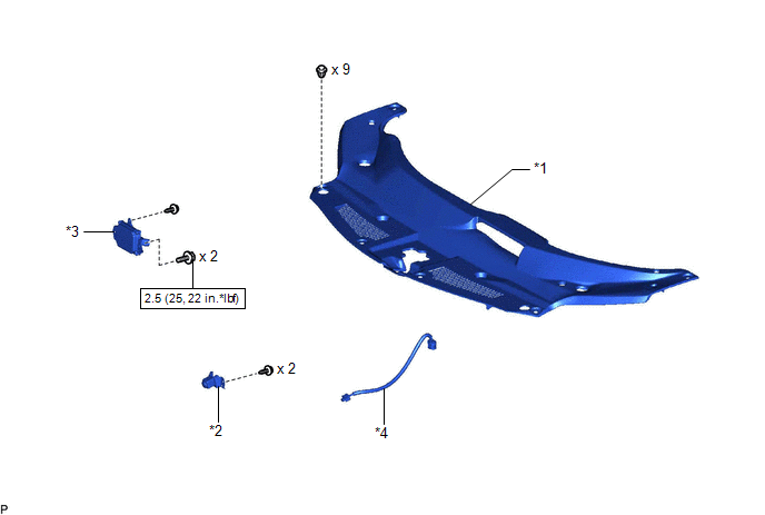
| *1 | COOL AIR INTAKE DUCT SEAL | *2 | FRONT TELEVISION CAMERA ASSEMBLY |
| *3 | MILLIMETER WAVE RADAR SENSOR ASSEMBLY | *4 | TELEVISION CAMERA WIRE |
.png) | N*m (kgf*cm, ft.*lbf): Specified torque | - | - |
Removal
REMOVAL
CAUTION / NOTICE / HINT
The necessary procedures (adjustment, calibration, initialization, or registration) that must be performed after parts are removed and installed, or replaced during front television camera assembly removal/installation are shown below.
Necessary Procedure After Parts Removed/Installed/Replaced| Replaced Part or Performed Procedure | Necessary Procedure | Effect/Inoperative Function when Necessary Procedure not Performed | Link |
|---|---|---|---|
| Front television camera assembly | Front television camera view adjustment | Panoramic view monitor system | |
PROCEDURE
1. PRECAUTION
Click here .gif)
2. REMOVE COOL AIR INTAKE DUCT SEAL
Click here
3. REMOVE MILLIMETER WAVE RADAR SENSOR ASSEMBLY
Click here
4. REMOVE FRONT TELEVISION CAMERA ASSEMBLY
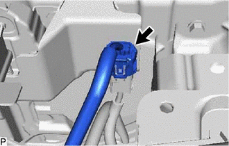
| (a) Disconnect the connector. |
|
| (b) Remove the 2 screws. |
|
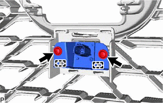
(c) Disengage the 2 guides and remove the front television camera assembly.
5. REMOVE TELEVISION CAMERA WIRE
HINT:
Perform this procedure only when replacement of the television camera wire is necessary.
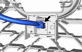
| (a) Disconnect the connector and remove the television camera wire. |
|
Installation
INSTALLATION
PROCEDURE
1. INSTALL TELEVISION CAMERA WIRE
HINT:
Perform this procedure only when replacement of the television camera wire is necessary.
(a) Connect the connector to install the television camera wire.
2. INSTALL FRONT TELEVISION CAMERA ASSEMBLY
| (a) Engage the 2 guides. |
|
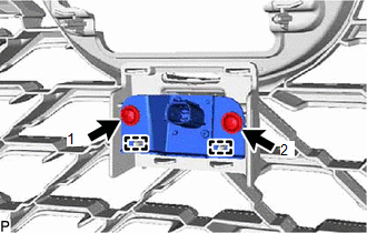
(b) Install the front television camera assembly with the 2 screws.
HINT:
Install the screws in the order shown in the illustration.
(c) Connect the connector.
3. INSTALL MILLIMETER WAVE RADAR SENSOR ASSEMBLY
Click here .gif)
4. INSTALL COOL AIR INTAKE DUCT SEAL
Click here
5. PERFORM INITIALIZATION
Click here
6. ADJUST FRONT TELEVISION CAMERA ASSEMBLY
Click here
 Removal
REMOVAL CAUTION / NOTICE / HINT The necessary procedures (adjustment, calibration, initialization, or registration) that must be performed after parts are removed and installed, or replaced during bli ...

Other materials:
Lexus RX (RX 350L, RX450h) 2016-2025 Repair Manual > Footwell Light: Inspection
INSPECTION PROCEDURE 1. INSPECT NO. 1 INTERIOR ILLUMINATION LIGHT ASSEMBLY LH (a) Apply battery voltage to the connector and check that the No. 1 interior illumination light LH comes on. OK: Measurement Condition Condition Specified Condition Battery positive (+) → 2 (B) Battery neg ...
Lexus RX (RX 350L, RX450h) 2016-2025 Repair Manual > Footwell Light: Components
COMPONENTS ILLUSTRATION *A for Driver Side *B for Front Passenger Side *1 COWL SIDE TRIM BOARD LH *2 COWL SIDE TRIM BOARD RH *3 FRONT DOOR SCUFF PLATE LH *4 FRONT DOOR SCUFF PLATE RH *5 NO. 1 INSTRUMENT PANEL UNDER COVER SUB-ASSEMBLY *6 NO. 1 INTERIOR ILLUMINA ...
Lexus RX (RX 350L, RX450h) 2016-{YEAR} Owners Manual
- For your information
- Pictorial index
- For safety and security
- Instrument cluster
- Operation of each component
- Driving
- Lexus Display Audio system
- Interior features
- Maintenance and care
- When trouble arises
- Vehicle specifications
- For owners
Lexus RX (RX 350L, RX450h) 2016-{YEAR} Repair Manual

0.014