Lexus RX (RX 350L, RX450h) 2016-2025 Repair Manual: Installation
INSTALLATION
PROCEDURE
1. INSTALL PARK/NEUTRAL POSITION SWITCH ASSEMBLY
(a) Move the shift lever to N.
(b) Temporarily install the park/neutral position switch assembly to the automatic transaxle case sub-assembly with the 2 bolts.
NOTICE:
Before installing the park/neutral position switch assembly, remove any dirt or rust on the manual valve lever shaft sub-assembly. Be sure to install the park/neutral position switch assembly straight along the manual valve lever shaft sub-assembly while being careful not to deform the plate spring that supports the manual valve lever shaft sub-assembly. If the plate spring is deformed, the park/neutral position switch assembly cannot be installed correctly.
(c) Install a new lock plate and the lock nut to the park/neutral position switch assembly.
Torque:
6.9 N·m {70 kgf·cm, 61 in·lbf}
(d) Temporarily install the transmission control shaft lever to the park/neutral position switch assembly.
| (e) Turn the transmission control shaft lever clockwise until it stops, then turn it counterclockwise 2 notches. |
|

(f) Remove the transmission control shaft lever from the park/neutral position switch assembly.
| (g) Align the protrusion with the neutral basic line. |
|
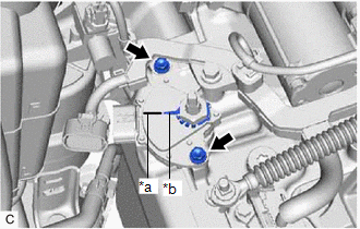
(h) Hold the park/neutral position switch assembly in that position and tighten the 2 bolts.
Torque:
5.4 N·m {55 kgf·cm, 48 in·lbf}
(i) Using a screwdriver, bend down the tabs of the lock plate.
(j) Install the transmission control shaft lever to the manual valve lever shaft sub-assembly with the nut.
Torque:
16 N·m {163 kgf·cm, 12 ft·lbf}
(k) Connect the park/neutral position switch assembly connector.
2. CONNECT TRANSMISSION CONTROL CABLE ASSEMBLY
(a) Connect the transmission control cable assembly to the transmission control shaft lever with the nut.
Torque:
12 N·m {122 kgf·cm, 9 ft·lbf}
NOTICE:
Before connecting the transmission control cable assembly, check that the park/neutral position switch assembly and shift lever are in neutral.
3. INSTALL BATTERY
(a) Install the battery clamp bolt to the battery carrier sub-assembly.
(b) Install the battery tray and battery.
(c) Install the battery insulator.
(d) Install the battery clamp sub-assembly with the bolt and nut.
Torque:
5.4 N·m {55 kgf·cm, 48 in·lbf}
(e) Connect the cable to the positive (+) battery terminal and tighten the nut.
Torque:
5.4 N·m {55 kgf·cm, 48 in·lbf}
(f) Engage the 2 claws to close the battery terminal cap.
4. CONNECT CABLE TO NEGATIVE BATTERY TERMINAL
NOTICE:
When disconnecting the cable, some systems need to be initialized after the cable is reconnected.
Click here .gif)
5. INSTALL INLET AIR CLEANER ASSEMBLY
Click here
6. INSTALL COOL AIR INTAKE DUCT SEAL
Click here
7. INSPECT PARK/NEUTRAL POSITION SWITCH ASSEMBLY OPERATION
Click here
8. INSPECT SHIFT LEVER POSITION
Click here
9. ADJUST SHIFT LEVER POSITION
Click here
 Adjustment
ADJUSTMENT PROCEDURE 1. SECURE VEHICLE (a) Fully apply the parking brake and chock a wheel. CAUTION:
Make sure to apply the parking brake and chock a wheel before performing this procedure.
If th ...
 Shift Lever
...
Other materials:
Lexus RX (RX 350L, RX450h) 2016-2025 Repair Manual > Rear Center Seat Outer Belt Assembly(w/ Rear No. 2 Seat): Inspection
INSPECTION PROCEDURE 1. INSPECT REAR CENTER SEAT OUTER BELT ASSEMBLY (a) After installing the rear center seat outer belt assembly, check the ELR function. NOTICE: Do not disassemble the retractor. (1) Move the seatback of the rear No. 1 seat assembly RH to the upright position. Check that the se ...
Lexus RX (RX 350L, RX450h) 2016-2025 Repair Manual > Driving Support Buzzer: Inspection
INSPECTION PROCEDURE 1. INSPECT SKID CONTROL BUZZER ASSEMBLY (a) Make sure that there is no looseness in the locking part and connecting part of the connector. (b) Disconnect the skid control buzzer assembly connector. (c) Check the connector and terminals for deformation and corrosio ...
Lexus RX (RX 350L, RX450h) 2016-{YEAR} Owners Manual
- For your information
- Pictorial index
- For safety and security
- Instrument cluster
- Operation of each component
- Driving
- Lexus Display Audio system
- Interior features
- Maintenance and care
- When trouble arises
- Vehicle specifications
- For owners
Lexus RX (RX 350L, RX450h) 2016-{YEAR} Repair Manual

0.0176