Lexus RX (RX 350L, RX450h) 2016-2025 Repair Manual: Terminals Of Ecu
TERMINALS OF ECU
CHECK FORWARD RECOGNITION CAMERA
.png)
NOTICE:
- DTCs may be output when connectors are disconnected during inspection. Therefore, be sure to clear the DTCs using the Techstream once the inspection has been completed.
- Do not apply excessive force to the forward recognition camera connector.
(a) Measure the voltage and resistance according to the value(s) in the table below.
| Terminal No. (Symbol) | Wiring Color | Terminal Description | Condition | Specified Condition |
|---|---|---|---|---|
| U14-1 (HTR) - U14-10 (GND) | B - BR | Forward recognition with heater hood sub-assembly operation signal | Engine switch on (IG) Forward recognition with heater hood sub-assembly not operating | 11 to 14 V |
| Engine switch on (IG) Forward recognition with heater hood sub-assembly operating | Below 1 V | |||
| U14-7 (IGB) - U14-10 (GND) | SB - BR | Power source | Engine switch on (IG) | 11 to 14 V |
| Engine switch off | Below 1 V | |||
| U14-8 (BZ) - U14-10 (GND) | W - BR | Skid control buzzer assembly output | Engine switch on (IG), buzzer not sounding | 11 to 14 V |
| Engine switch on (IG), buzzer sounding | Below 1 V | |||
| U14-10 (GND) - Body ground | BR - Body ground | Ground | Always | Below 1 Ω |
(b) Check for pulses according to the value(s) in the table below.
HINT:
If the waveform is not similar to that shown in the illustration, a malfunction of a CAN bus line, terminating resistor, or the forward recognition camera is suspected.
| Terminal No. (Symbol) | Wiring Color | Terminal Description | Condition | Specified Condition |
|---|---|---|---|---|
| U14-5 (CA1P) - U14-10 (GND) | V - BR | CAN communication signal | Engine switch on (IG) | Pulse generation (See waveform 1) |
| U14-6 (CANH) - U14-10 (GND) | B - BR | CAN communication signal | Engine switch on (IG) | Pulse generation (See waveform 1) |
| U14-11 (CA1N) - U14-10 (GND) | P - BR | CAN communication signal | Engine switch on (IG) | Pulse generation (See waveform 2) |
| U14-12 (CANL) - U14-10 (GND) | W - BR | CAN communication signal | Engine switch on (IG) | Pulse generation (See waveform 2) |
(1) Waveform 1
| Item | Content |
|---|---|
| Tester Connection |
|
| Tool Setting | 1 V/DIV., 10 μs./DIV. |
| Condition | Engine switch on (IG) |
HINT:
The waveform varies depending on the CAN communication signal.
.png)
(2) Waveform 2
| Item | Content |
|---|---|
| Tester Connection |
|
| Tool Setting | 1 V/DIV., 10 μs./DIV. |
| Condition | Engine switch on (IG) |
HINT:
The waveform varies depending on the CAN communication signal.
.png)
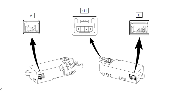
CHECK STEERING VIBRATION ECU
NOTICE:
DTCs may be output when connectors are disconnected during inspection. Therefore, be sure to clear the DTCs using the Techstream once the inspection has been completed.
(a) Measure the voltage and resistance according to the value(s) in the table below.
| Terminal No. (Symbol) | Terminal Description | Condition | Specified Condition |
|---|---|---|---|
| z11-4 (IG) - z11-1 (GND) | Power source | Engine switch on (IG) | Pulse generation |
| Engine switch off | Below 1 V | ||
| B-1 (M+) - z11-1 (GND) | Steering vibration operation signal | Engine switch on (IG) Steering vibration operating | 11 to 14 V |
| Engine switch on (IG) Steering vibration not operating | Below 1 V | ||
| z11-1 (GND) - Body ground | Ground | Always | Below 1 Ω |
(b) Measure the waveform according to the value(s) in the table below.
| Terminal No. (Symbol) | Terminal Description | Condition | Specified Condition |
|---|---|---|---|
| A-2 (LDA) - z11-1 (GND) | LIN communication signal | Engine switch on (IG) | Pulse generation |
 Problem Symptoms Table
PROBLEM SYMPTOMS TABLE HINT:
Use the table below to help determine the cause of problem symptoms. If multiple suspected areas are listed, the potential causes of the symptoms are listed in order of ...
 Data List / Active Test
DATA LIST / ACTIVE TEST NOTICE: In the table below, the values listed under "Normal Condition" are reference values. Do not depend solely on these reference values when deciding whether a part is faul ...
Other materials:
Lexus RX (RX 350L, RX450h) 2016-2025 Repair Manual > Differential Case: Disassembly
DISASSEMBLY PROCEDURE 1. REMOVE DIFFERENTIAL CASE TAPERED ROLLER BEARING (FRONT SIDE) (a) Using SST, remove the differential case tapered roller bearing (front side inner race) from the differential case assembly. SST: 09950-00020 SST: 09950-00030 SST: 09950-40011 09957-04010 SST: 09950-60010 099 ...
Lexus RX (RX 350L, RX450h) 2016-2025 Repair Manual > Rear No. 1 Seat Assembly (for 60/40 Split Seat Type Rh Side): Removal
REMOVAL CAUTION / NOTICE / HINT The necessary procedures (adjustment, calibration, initialization or registration) that must be performed after parts are removed and installed, or replaced during rear No. 1 seat assembly removal/installation are shown below. Necessary Procedure After Parts Removed/I ...
Lexus RX (RX 350L, RX450h) 2016-{YEAR} Owners Manual
- For your information
- Pictorial index
- For safety and security
- Instrument cluster
- Operation of each component
- Driving
- Lexus Display Audio system
- Interior features
- Maintenance and care
- When trouble arises
- Vehicle specifications
- For owners
Lexus RX (RX 350L, RX450h) 2016-{YEAR} Repair Manual

0.0137