Lexus RX (RX 350L, RX450h) 2016-2025 Repair Manual: Kick Sensor Circuit (B2205)
DESCRIPTION
B2205 is output when the multiplex network door ECU detects that the kick door control sensor is stuck on.
| DTC No. | Detection Item | DTC Detection Condition | Trouble Area |
|---|---|---|---|
| B2205 | Kick Sensor Circuit | One of the following conditions is met for approximately 60 seconds or more:
|
|
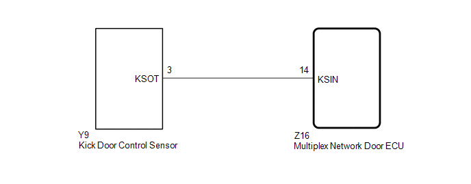
WIRING DIAGRAM
CAUTION / NOTICE / HINT
NOTICE:
- Before troubleshooting, make sure that the kick door control sensor is not damaged.
-
Before troubleshooting, be sure to read Precautions for Hands Free Power Back Door.
Click here
.gif)
-
If the multiplex network door ECU has been removed and installed or replaced, or if any of the connectors have been disconnected, initialize the power back door system.
Click here
-
After performing work, using the Techstream, read the Data List item "Kick Sensor Connection" and check that the kick door control sensor is connected.
Click here
-
Check the smart access system (for Entry Function) first before troubleshooting the power back door system.
Click here
PROCEDURE
| 1. | CHECK FOR DTC |
(a) Connect the Techstream to the DLC3.
(b) Turn the engine switch on (IG).
(c) Turn the Techstream on.
(d) Enter the following menus: Body Electrical / Back Door / Trouble Codes.
(e) Clear the DTCs.
Body Electrical > Back Door > Clear DTCs(f) Recheck for DTCs.
Body Electrical > Back Door > Trouble CodesOK:
DTC B2205 is not output.
| OK | .gif) | USE SIMULATION METHOD TO CHECK |
|
.gif)
| 2. | CHECK FOR DTC |
(a) Disconnect the Y9 kick door control sensor connector.
(b) Wait for approximately 60 seconds.
(c) Clear the DTCs.
Body Electrical > Back Door > Clear DTCs(d) Check for DTCs.
Body Electrical > Back Door > Trouble CodesOK:
DTC B2205 is not output.
| OK | | REPLACE KICK DOOR CONTROL SENSOR |
|
| 3. | CHECK HARNESS AND CONNECTOR (MULTIPLEX NETWORK DOOR ECU - KICK DOOR CONTROL SENSOR) |
(a) Disconnect the Z16 multiplex network door ECU connector.
(b) Measure the resistance according to the value(s) in the table below.
Standard Resistance:
| Tester Connection | Condition | Specified Condition |
|---|---|---|
| Z16-14 (KSIN) or Y9-3 (KSOT) - Body ground | Always | 10 kΩ or higher |
| OK | | REPLACE MULTIPLEX NETWORK DOOR ECU |
| NG | | REPAIR OR REPLACE HARNESS OR CONNECTOR |
 Data List / Active Test
DATA LIST / ACTIVE TEST DATA LIST NOTICE: In the table below, the values listed under "Normal Condition" are reference values. Do not depend solely on these reference values when deciding whether a pa ...
 Back Door Motor Circuit (B2220)
DESCRIPTION This DTC is stored when the multiplex network door ECU detects a malfunction of the motor built-into the power back door unit assembly set LH or power back door unit assembly set RH. DT ...
Other materials:
Lexus RX (RX 350L, RX450h) 2016-2025 Repair Manual > Audio And Visual System (for 12.3 Inch Display): System Description
SYSTEM DESCRIPTION DISC PLAYER OUTLINE (a) A disc player uses a laser pickup to read digital signals recorded on a disc. By converting the digital signals to analog, it can play music, video and audio. CAUTION: Do not look directly at the laser pickup because the disc player uses an invisible laser ...
Lexus RX (RX 350L, RX450h) 2016-2025 Repair Manual > Automatic Transaxle System: Pressure Control Solenoid "D" Circuit Open (P271313)
DESCRIPTION Refer to DTC P27137F. Click here DTC No. Detection Item DTC Detection Condition Trouble Area MIL Memory Note P271313 Pressure Control Solenoid "D" Circuit Open 1. Diagnosis Condition 2. Malfunction Status 3. Malfunction Time 4. Other
Engine is running
Shif ...
Lexus RX (RX 350L, RX450h) 2016-{YEAR} Owners Manual
- For your information
- Pictorial index
- For safety and security
- Instrument cluster
- Operation of each component
- Driving
- Lexus Display Audio system
- Interior features
- Maintenance and care
- When trouble arises
- Vehicle specifications
- For owners
Lexus RX (RX 350L, RX450h) 2016-{YEAR} Repair Manual

0.0145