Lexus RX (RX 350L, RX450h) 2016-2025 Repair Manual: Disassembly
DISASSEMBLY
PROCEDURE
1. REMOVE FRONT BUMPER ARM HOLE COVER LH (for Type A)
(a) Remove the screw and clip.

.png) | Screw |
.png) | Clip |
| (b) Disengage the 3 guides to remove the front bumper arm hole cover LH. |
|

2. REMOVE FRONT BUMPER ARM HOLE COVER LH (for Type B)
(a) Remove the screw and clip.

| | Screw |
| | Clip |
| (b) Disengage the 3 guides to remove the front bumper arm hole cover LH. |
|

3. REMOVE FRONT BUMPER HOLE COVER ASSEMBLY LH (w/o Fog Light)
(a) w/ Headlight Cleaner System:
| (1) Disengage the clamp. |
|

(b) Remove the clip.

| | Clip |
| | Screw |
(c) Remove the 2 screws and front bumper hole cover assembly LH.
4. REMOVE FRONT BUMPER HOLE COVER ASSEMBLY RH (w/o Fog Light)
HINT:
Use the same procedure as for the LH side.
5. REMOVE CONNECTOR COVER (w/o Fog Light)
HINT:
Use the same procedure for all connector covers.
| (a) Disengage the clamp to remove the connector cover. |
|

6. REMOVE FOG LIGHT ASSEMBLY LH (w/ Fog Light)
Click here .gif)
7. REMOVE FOG LIGHT ASSEMBLY RH (w/ Fog Light)
HINT:
Use the same procedure as for the LH side.
8. REMOVE MILLIMETER WAVE RADAR SENSOR ASSEMBLY
Click here
9. REMOVE TELEVISION CAMERA WIRE (w/ Panoramic View Monitor System)
| (a) Disconnect the connector to remove the television camera wire. |
|

10. REMOVE FRONT TELEVISION CAMERA ASSEMBLY (w/ Panoramic View Monitor System)
Click here
11. REMOVE FRONT CENTER ULTRASONIC SENSOR (w/ Intuitive Parking Assist System)
Click here
12. REMOVE FRONT CORNER ULTRASONIC SENSOR (w/ Intuitive Parking Assist System)
Click here
13. REMOVE FRONT CORNER ULTRASONIC SENSOR RETAINER (w/ Intuitive Parking Assist System)
Click here
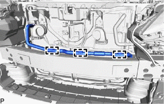
14. REMOVE NO. 4 ENGINE ROOM WIRE (w/ Intuitive Parking Assist System)
(a) Disengage the 12 clamps to remove the No. 4 engine room wire.

15. REMOVE ULTRASONIC SENSOR CLIP (w/ Intuitive Parking Assist System)
HINT:
- Use the same procedure for all ultrasonic sensor clips.
- When removing the ultrasonic sensor clip, heat the front bumper assembly and ultrasonic sensor clip using a heat light.
Heating Temperature:
| Item | Temperature |
|---|---|
| Ultrasonic Sensor Clip and Front Bumper Assembly | 20 to 30°C (68 to 86°F) |
CAUTION:
- Do not touch the heat light and heated parts, touching the heat light may result in burns.
- Touching heated parts for a long time may result in burns.
.png)
| *a | Heated Part |
| *b | Heat Light |
NOTICE:
Do not heat the front bumper assembly or ultrasonic sensor clip excessively.
(a) Using a heat light, heat the front bumper assembly and ultrasonic sensor clip.
| (b) Remove the ultrasonic sensor clip. |
|

16. REMOVE HEADLIGHT WASHER COVER LH (w/ Headlight Cleaner System)
Click here
17. REMOVE HEADLIGHT WASHER COVER RH (w/ Headlight Cleaner System)
HINT:
Use the same procedure as for the LH side.
18. REMOVE HEADLIGHT WASHER ACTUATOR SUB-ASSEMBLY LH (w/ Headlight Cleaner System)
Click here
19. REMOVE HEADLIGHT WASHER ACTUATOR SUB-ASSEMBLY RH (w/ Headlight Cleaner System)
HINT:
Use the same procedure as for the LH side.
20. REMOVE HEADLIGHT CLEANER HOSE (w/ Headlight Cleaner System)
(a) Disengage the 8 clamps and remove the headlight cleaner hose.

21. REMOVE NO. 2 WASHER BRACKET (w/ Headlight Cleaner System)
HINT:
When removing the No. 2 washer bracket, heat the No. 2 washer bracket and front bumper assembly using a heat light.
Heating Temperature:
| Item | Temperature |
|---|---|
| No. 2 Washer Bracket and Front Bumper Assembly | 20 to 30°C (68 to 86°F) |
CAUTION:
- Do not touch the heat light and heated parts, touching the heat light may result in burns.
- Touching heated parts for a long time may result in burns.
| *a | Heated Part |
| *b | Heat Light |
NOTICE:
Do not heat the No. 2 washer bracket or front bumper assembly excessively.
(a) Using a heat light, heat the No. 2 washer bracket and front bumper assembly.
| (b) Remove the No. 2 washer bracket. |
|

22. REMOVE NO. 1 WASHER BRACKET (w/ Headlight Cleaner System)
HINT:
Use the same procedure for the No. 2 washer bracket.
23. REMOVE NO. 1 MOULDING TAPE
| (a) Remove the No. 1 moulding tape. HINT: Use the same procedure for the RH side and LH side. |
|

24. REMOVE FRONT BUMPER HOLE COVER LH (except F-Sport)
| (a) Disengage the 5 claws. |
|

(b) Disengage the hook to remove the front bumper hole cover LH.
25. REMOVE FRONT BUMPER HOLE COVER LH (for F-Sport)
| (a) Disengage the 3 claws. |
|

(b) Disengage the hook to remove the front bumper hole cover LH.
26. REMOVE FRONT BUMPER HOLE COVER RH
HINT:
Use the same procedure as for the LH side.
27. REMOVE LOWER SIDE RADIATOR GRILLE LH (except F-Sport)
| (a) Disengage the 5 claws to remove the lower side radiator grille LH. |
|

28. REMOVE LOWER SIDE RADIATOR GRILLE LH (for F-Sport)
| (a) Remove the 4 clips. |
|

(b) Disengage the 3 claws to remove the lower side radiator grille LH.
29. REMOVE LOWER SIDE RADIATOR GRILLE RH
HINT:
Use the same procedure as for the LH side.
30. REMOVE FRONT BUMPER EXTENSION MOUNTING BRACKET (except F-Sport)
| (a) Remove the 2 screws. |
|

(b) Disengage the 2 claws to remove the front bumper extension mounting bracket as shown in the illustration.

.png) | Remove in this Direction |
31. REMOVE FRONT BUMPER EXTENSION MOUNTING BRACKET (for F-Sport)
| (a) Remove the 2 screws. |
|

(b) Disengage the 2 claws to remove the front bumper extension mounting bracket as shown in the illustration.

| | Remove in this Direction |
32. REMOVE RADIATOR GRILLE (OR FRONT PANEL) EMBLEM
| (a) Remove the 2 screws. |
|

(b) Disengage the claw and guide as shown in the illustration to remove the radiator grille (or front panel) emblem.

| | Remove in this Direction |
33. REMOVE HOOD TO RADIATOR GRILLE SEAL
(a) Disengage the 18 clips to remove the hood to radiator grille seal.

34. REMOVE INNER RADIATOR GRILLE
(a) Remove the 7 screws and 2 clips.

| | Screw | | Clip |
(b) Disengage the 3 claws and 7 guides to remove the inner radiator grille.

35. REMOVE RADIATOR GRILLE SUB-ASSEMBLY
(a) Remove the 2 clips and 12 screws.

(b) Disengage the 10 clips and 10 guides to remove the radiator grille sub-assembly.

36. REMOVE NO. 1 RADIATOR GRILLE MOULDING
(a) Remove the 2 screws.

(b) Disengage the 10 claws and 2 clips to remove the No. 1 radiator grille moulding.

37. REMOVE NO. 2 RADIATOR GRILLE MOULDING
(a) Remove the screw.

(b) Disengage the 7 clips to remove the No. 2 radiator grille moulding.
38. REMOVE FRONT BUMPER GUARD COVER LH (except F-Sport)
(a) Remove the 3 screws and clip.

| | Screw |
| | Clip |
| (b) Remove the 2 clips. |
|

| (c) Disengage the 4 claws and 3 guides to remove the front bumper guard cover LH. |
|

39. REMOVE FRONT BUMPER GUARD COVER RH (except F-Sport)
HINT:
Use the same procedure as for the LH side.
40. REMOVE FRONT BUMPER GUARD (except F-Sport)
(a) Remove the 4 clips.

(b) Disengage the 6 claws and 4 guides to remove the front bumper guard.

41. REMOVE FRONT BUMPER SIDE MOULDING LH (for F-Sport)
| (a) Remove the 2 screws. |
|

(b) Disengage the 2 claws to remove the front bumper side moulding LH.
42. REMOVE FRONT BUMPER SIDE MOULDING RH (for F-Sport)
HINT:
Use the same procedure as for the LH side.
43. REMOVE FRONT BUMPER EXTENSION SUB-ASSEMBLY (for F-Sport)
(a) Remove the 2 screws and 2 clips.

| | Screw | | Clip |
(b) Remove the 8 clips.

(c) Disengage the 10 claws and 8 guides to remove the front bumper extension sub-assembly.

44. REMOVE FRONT BUMPER ENERGY ABSORBER
(a) Remove the front bumper energy absorber as shown in the illustration.

| | Remove in this Direction |
45. REMOVE FRONT BUMPER REINFORCEMENT SUB-ASSEMBLY
| (a) Disengage the 3 clamps. |
|
| (b) Remove the 2 clips. |
|

| (c) Remove the 6 bolts and front bumper reinforcement sub-assembly. |
|

46. REMOVE FRONT BUMPER SIDE RETAINER LH
| (a) Remove the bolt. |
|

(b) Disengage the clip as shown in the illustration.

| | Remove in this Direction (1) |
.png) | Remove in this Direction (2) |
(c) Disengage the claw as shown in the illustration to remove the front bumper side retainer LH.
47. REMOVE FRONT BUMPER SIDE RETAINER RH
HINT:
Use the same procedure as for the LH side.
 Removal
REMOVAL CAUTION / NOTICE / HINT The necessary procedures (adjustment, calibration, initialization, or registration) that must be performed after parts are removed and installed, or replaced during fro ...
 Reassembly
REASSEMBLY PROCEDURE 1. INSTALL FRONT BUMPER SIDE RETAINER LH (a) Engage the claw as shown in the illustration. Install in this Direction (1) Install in this Direction (2) (b) Engage ...
Other materials:
Lexus RX (RX 350L, RX450h) 2016-2025 Repair Manual > Power Steering System: Fail-safe Chart
FAIL-SAFE CHART If a problem occurs in the power steering system, the power steering assist will be stopped or the amount of power assist will be decreased to protect the system. Power Steering System Malfunction Fail-safe Operation EPS warning light Buzzer
Torque sensor (electric po ...
Lexus RX (RX 350L, RX450h) 2016-2025 Repair Manual > Wiper And Washer System: Rain Sensor Malfunction (B1400)
DESCRIPTION This DTC is stored when the rain sensor detects an internal malfunction. DTC No. Detection Item DTC Detection Condition Trouble Area Memory DTC Output from B1400 Rain Sensor Malfunction
When the battery voltage is 9.5 V or more, the rain sensor temperature is abno ...
Lexus RX (RX 350L, RX450h) 2016-{YEAR} Owners Manual
- For your information
- Pictorial index
- For safety and security
- Instrument cluster
- Operation of each component
- Driving
- Lexus Display Audio system
- Interior features
- Maintenance and care
- When trouble arises
- Vehicle specifications
- For owners
Lexus RX (RX 350L, RX450h) 2016-{YEAR} Repair Manual

0.0138