Lexus RX (RX 350L, RX450h) 2016-2025 Repair Manual: Cornering Light Circuit
DESCRIPTION
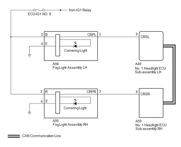
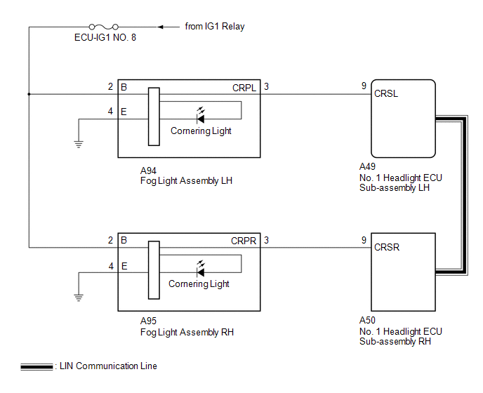
The No. 1 headlight ECU sub-assembly controls the cornering lights.
WIRING DIAGRAM
for Multiple Beam Headlight
for Single Beam Headlight
CAUTION / NOTICE / HINT
NOTICE:
-
If the No. 1 headlight ECU sub-assembly LH has been replaced, it is necessary to synchronize the vehicle information and initialize the No. 1 headlight ECU sub-assembly LH.
Click here
.gif)
-
If the headlight assembly LH has been replaced, it is necessary to synchronize the vehicle information and initialize the No. 1 headlight ECU sub-assembly LH.*
Click here
- When replacing the No. 1 headlight ECU sub-assembly LH, always replace it with a new one. If a No. 1 headlight ECU sub-assembly LH which was installed to another vehicle is used, the information stored in it will not match the information from the vehicle and a DTC may be stored.
- When replacing the headlight assembly LH, always replace it with a new one. If a headlight assembly LH which was installed to another vehicle is used, the information stored in it will not match the information from the vehicle and a DTC may be stored.*
-
Check the fuses for circuits related to this system before performing the following inspection procedure.
- *: for TMMC Made
PROCEDURE
| 1. | CHECK LIGHTS |
(a) Check the illumination of each cornering lights.
| Result | Proceed to |
|---|---|
| LH side cornering light does not illuminate | A |
| RH side cornering light does not illuminate | B |
| B | .gif) | GO TO STEP 9 |
|
.gif)
| 2. | CONFIRM MODEL |
(a) Choose the model to be inspected.
| Result | Proceed to |
|---|---|
| for Multiple Beam Headlight | A |
| for Single Beam Headlight | B |
| B | | GO TO STEP 4 |
|
| 3. | PERFORM ACTIVE TEST USING TECHSTREAM |
(a) Connect the Techstream to the DLC3.
(b) Turn the engine switch on (IG).
(c) Turn the Techstream on.
(d) Enter the following menus: Body Electrical / AFS / Active Test.
(e) Perform the Active Test according to the display on the Techstream.
Body Electrical > AFS > Active Test| Tester Display | Measurement Item | Control Range | Diagnostic Note |
|---|---|---|---|
| Cornering Light | Cornering lights | OFF or ON | - |
| Tester Display |
|---|
| Cornering Light |
OK:
Cornering lights illuminate.
| OK | | PROCEED TO NEXT SUSPECTED AREA SHOWN IN PROBLEM SYMPTOMS TABLE |
| NG | | GO TO STEP 5 |
| 4. | PERFORM ACTIVE TEST USING TECHSTREAM |
(a) Connect the Techstream to the DLC3.
(b) Turn the engine switch on (IG).
(c) Turn the Techstream on.
(d) Enter the following menus: Body Electrical / HL AutoLeveling / Active Test.
(e) Perform the Active Test according to the display on the Techstream.
Body Electrical > HL AutoLeveling > Active Test| Tester Display | Measurement Item | Control Range | Diagnostic Note |
|---|---|---|---|
| Cornering Light | Cornering lights | OFF or ON | - |
| Tester Display |
|---|
| Cornering Light |
OK:
Cornering lights illuminate.
| OK | | PROCEED TO NEXT SUSPECTED AREA SHOWN IN PROBLEM SYMPTOMS TABLE |
|
| 5. | CHECK HARNESS AND CONNECTOR (POWER SOURCE - CORNERING LIGHT (FOG LIGHT ASSEMBLY LH)) |
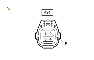
| *a | Front view of wire harness connector (to Cornering Light (Fog Light Assembly LH)) |
(a) Disconnect the A94 cornering light (fog light assembly LH) connector.
(b) Measure the voltage according to the value(s) in the table below.
Standard Voltage:
| Tester Connection | Condition | Specified Condition |
|---|---|---|
| A94-2 (B) - Body ground | Engine switch on (IG) | 11 to 14 V |
| NG | | REPAIR OR REPLACE HARNESS OR CONNECTOR |
|
| 6. | CHECK HARNESS AND CONNECTOR (CORNERING LIGHT (FOG LIGHT ASSEMBLY LH) - BODY GROUND) |
(a) Measure the resistance according to the value(s) in the table below.
Standard Resistance:
| Tester Connection | Condition | Specified Condition |
|---|---|---|
| A94-4 (E) - Body ground | Always | Below 1 Ω |
| NG | | REPAIR OR REPLACE HARNESS OR CONNECTOR |
|
| 7. | CHECK HARNESS AND CONNECTOR (CORNERING LIGHT (FOG LIGHT ASSEMBLY LH) - NO. 1 HEADLIGHT ECU SUB-ASSEMBLY LH) |
(a) Disconnect the A49 No. 1 headlight ECU sub-assembly LH connector.
(b) Measure the resistance according to the value(s) in the table below.
Standard Resistance:
| Tester Connection | Condition | Specified Condition |
|---|---|---|
| A94-3 (CRPL) - A49-9 (CRSL) | Always | Below 1 Ω |
| A94-3 (CRPL) or A49-9 (CRSL) - Body ground | Always | 10 kΩ or higher |
| NG | | REPAIR OR REPLACE HARNESS OR CONNECTOR |
|
| 8. | INSPECT CORNERING LIGHT (FOG LIGHT ASSEMBLY LH) |
(a) Remove the cornering light (fog light assembly LH).
Click here
(b) Inspect the cornering light (fog light assembly LH).
Click here
| OK | | REPLACE NO. 1 HEADLIGHT ECU SUB-ASSEMBLY LH |
| NG | | REPLACE CORNERING LIGHT (FOG LIGHT ASSEMBLY LH) |
| 9. | CONFIRM MODEL |
(a) Choose the model to be inspected.
| Result | Proceed to |
|---|---|
| for Multiple Beam Headlight | A |
| for Single Beam Headlight | B |
| B | | GO TO STEP 11 |
|
| 10. | PERFORM ACTIVE TEST USING TECHSTREAM |
(a) Connect the Techstream to the DLC3.
(b) Turn the engine switch on (IG).
(c) Turn the Techstream on.
(d) Enter the following menus: Body Electrical / AFS / Active Test.
(e) Perform the Active Test according to the display on the Techstream.
Body Electrical > AFS > Active Test| Tester Display | Measurement Item | Control Range | Diagnostic Note |
|---|---|---|---|
| Cornering Light | Cornering lights | OFF or ON | - |
| Tester Display |
|---|
| Cornering Light |
OK:
Cornering lights illuminate.
| OK | | PROCEED TO NEXT SUSPECTED AREA SHOWN IN PROBLEM SYMPTOMS TABLE |
| NG | | GO TO STEP 12 |
| 11. | PERFORM ACTIVE TEST USING TECHSTREAM |
(a) Connect the Techstream to the DLC3.
(b) Turn the engine switch on (IG).
(c) Turn the Techstream on.
(d) Enter the following menus: Body Electrical / HL AutoLeveling / Active Test.
(e) Perform the Active Test according to the display on the Techstream.
Body Electrical > HL AutoLeveling > Active Test| Tester Display | Measurement Item | Control Range | Diagnostic Note |
|---|---|---|---|
| Cornering Light | Cornering lights | OFF or ON | - |
| Tester Display |
|---|
| Cornering Light |
OK:
Cornering lights illuminate.
| OK | | PROCEED TO NEXT SUSPECTED AREA SHOWN IN PROBLEM SYMPTOMS TABLE |
|
| 12. | CHECK HARNESS AND CONNECTOR (POWER SOURCE - CORNERING LIGHT (FOG LIGHT ASSEMBLY RH)) |
.png)
| *a | Front view of wire harness connector (to Cornering Light (Fog Light Assembly RH)) |
(a) Disconnect the A95 cornering light (fog light assembly RH) connector.
(b) Measure the voltage according to the value(s) in the table below.
Standard Voltage:
| Tester Connection | Condition | Specified Condition |
|---|---|---|
| A95-2 (B) - Body ground | Engine switch on (IG) | 11 to 14 V |
| NG | | REPAIR OR REPLACE HARNESS OR CONNECTOR |
|
| 13. | CHECK HARNESS AND CONNECTOR (CORNERING LIGHT (FOG LIGHT ASSEMBLY RH) - BODY GROUND) |
(a) Measure the resistance according to the value(s) in the table below.
Standard Resistance:
| Tester Connection | Condition | Specified Condition |
|---|---|---|
| A95-4 (E) - Body ground | Always | Below 1 Ω |
| NG | | REPAIR OR REPLACE HARNESS OR CONNECTOR |
|
| 14. | CHECK HARNESS AND CONNECTOR (CORNERING LIGHT (FOG LIGHT ASSEMBLY RH) - NO. 1 HEADLIGHT ECU SUB-ASSEMBLY RH) |
(a) Disconnect the A50 No. 1 headlight ECU sub-assembly RH connector.
(b) Measure the resistance according to the value(s) in the table below.
Standard Resistance:
| Tester Connection | Condition | Specified Condition |
|---|---|---|
| A95-3 (CRPR) - A50-9 (CRSR) | Always | Below 1 Ω |
| A95-3 (CRPR) or A50-9 (CRSR) - Body ground | Always | 10 kΩ or higher |
| NG | | REPAIR OR REPLACE HARNESS OR CONNECTOR |
|
| 15. | INSPECT CORNERING LIGHT (FOG LIGHT ASSEMBLY RH) |
(a) Remove the cornering light (fog light assembly RH).
Click here
(b) Inspect the cornering light (fog light assembly RH).
Click here
| OK | | REPLACE NO. 1 HEADLIGHT ECU SUB-ASSEMBLY RH |
| NG | | REPLACE CORNERING LIGHT (FOG LIGHT ASSEMBLY RH) |
 Taillight Relay Circuit
DESCRIPTION The main body ECU (multiplex network body ECU) controls the operation of the TAIL relay. WIRING DIAGRAM CAUTION / NOTICE / HINT NOTICE:
Inspect the fuses for circuits related to this s ...
 High Beam Headlight Circuit
DESCRIPTION The No. 1 headlight ECU sub-assembly controls the high beam headlights. WIRING DIAGRAM for Multiple Beam Headlight for Single Beam Headlight CAUTION / NOTICE / HINT NOTICE:
If the No. ...
Other materials:
Lexus RX (RX 350L, RX450h) 2016-2025 Repair Manual > Rear Airbag Sensor (w/ Rear No. 2 Seat): Installation
INSTALLATION CAUTION / NOTICE / HINT HINT:
Use the same procedure for the RH side and LH side.
The following procedure is for the LH side.
PROCEDURE 1. INSTALL REAR AIRBAG SENSOR (a) Check that the engine switch is off. (b) Check that the cable is disconnected from the negative (-) battery t ...
Lexus RX (RX 350L, RX450h) 2016-2025 Repair Manual > Theft Deterrent System: How To Proceed With Troubleshooting
CAUTION / NOTICE / HINT HINT:
Use this procedure to troubleshoot the theft deterrent system.
*: Use the Techstream.
PROCEDURE 1. VEHICLE BROUGHT TO WORKSHOP
NEXT 2. CUSTOMER PROBLEM ANALYSIS (a) Interview the customer to confirm the problem. Click here ...
Lexus RX (RX 350L, RX450h) 2016-{YEAR} Owners Manual
- For your information
- Pictorial index
- For safety and security
- Instrument cluster
- Operation of each component
- Driving
- Lexus Display Audio system
- Interior features
- Maintenance and care
- When trouble arises
- Vehicle specifications
- For owners
Lexus RX (RX 350L, RX450h) 2016-{YEAR} Repair Manual

0.0158