Lexus RX (RX 350L, RX450h) 2016-2025 Repair Manual: Driver Side Power Window does not Operate with Power Window Master Switch
DESCRIPTION
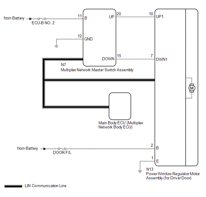
When the engine switch is on (IG), the power window regulator motor assembly (for driver door) is operated by the multiplex network master switch assembly. The power window regulator motor assembly (for driver door) has motor, regulator and ECU functions.
WIRING DIAGRAM
CAUTION / NOTICE / HINT
NOTICE:
-
The power window control system uses the LIN communication system. Inspect the communication function by following How to Proceed with Troubleshooting. Troubleshoot the power window control system after confirming that the communication system is functioning properly.
Click here
.gif)
-
If the power window regulator motor assembly (for driver door) has been replaced with a new one, initialize the power window control system.
Click here
- Inspect the fuses for circuits related to this system before performing the following procedure.
-
Before replacing the main body ECU (multiplex network body ECU), refer to Registration.
Click here
PROCEDURE
| 1. | READ VALUE USING TECHSTREAM (MAIN BODY) |
(a) Connect the Techstream to the DLC3.
(b) Turn the engine switch on (IG).
(c) Turn the Techstream on.
(d) Enter the following menus: Body Electrical / Main Body / Data List.
(e) Read the Data List according to the display on the Techstream.
Body Electrical > Main Body > Data List| Tester Display | Measurement Item | Range | Normal Condition | Diagnostic Note |
|---|---|---|---|---|
| Communication D-Door Motor | Connection status between power window regulator motor assembly (for driver door) and main body ECU (multiplex network body ECU) | STOP or OK | STOP: Communication stopped OK: Normal communication | - |
| Communication Master SW | Connection status between multiplex network master switch assembly and main body ECU (multiplex network body ECU) | STOP or OK | STOP: Communication stopped OK: Normal communication | - |
| Tester Display |
|---|
| Communication D-Door Motor |
| Communication Master SW |
OK:
OK is displayed for each Data List item above.
| NG | .gif) | GO TO LIN COMMUNICATION SYSTEM (Proceed to How to Proceed with Troubleshooting) |
|
.gif)
| 2. | READ VALUE USING TECHSTREAM (D-DOOR MOTOR) |
(a) Enter the following menus: Body Electrical / D-Door Motor / Data List.
(b) Read the Data List according to the display on the Techstream.
Body Electrical > D-Door Motor > Data List| Tester Display | Measurement Item | Range | Normal Condition | Diagnostic Note |
|---|---|---|---|---|
| D Door P/W Up SW | Driver door power window manual up switch signal | OFF or ON | OFF: Driver door power window manual up switch not being operated ON: Driver door power window manual up switch being operated | - |
| D Door P/W Down SW | Driver door power window manual down switch signal | OFF or ON | OFF: Driver door power window manual down switch not being operated ON: Driver door power window manual down switch being operated | - |
| Tester Display |
|---|
| D Door P/W Up SW |
| D Door P/W Down SW |
OK:
On the Techstream screen, ON or OFF is displayed accordingly.
| NG | | GO TO STEP 4 |
|
| 3. | PERFORM ACTIVE TEST USING TECHSTREAM (D-DOOR MOTOR) |
(a) Enter the following menus: Body Electrical / D-Door Motor / Active Test.
(b) Perform the Active Test according to the display on the Techstream.
CAUTION:
Be careful to avoid injuries as this test causes vehicle parts to move. During the Active Test, the jam protection function will not operate.
Body Electrical > D-Door Motor > Active Test| Tester Display | Measurement Item | Control Range | Diagnostic Note |
|---|---|---|---|
| Power Window | Power window | OFF / DOWN / UP | - |
| Tester Display |
|---|
| Power Window |
OK:
Driver door power window operates normally.
| OK | | REPLACE MAIN BODY ECU (MULTIPLEX NETWORK BODY ECU) |
| NG | | REPLACE POWER WINDOW REGULATOR MOTOR ASSEMBLY (FOR DRIVER DOOR) |
| 4. | CHECK HARNESS AND CONNECTOR (MULTIPLEX NETWORK MASTER SWITCH ASSEMBLY - POWER WINDOW REGULATOR MOTOR ASSEMBLY (FOR DRIVER DOOR)) |
(a) Disconnect the N7 multiplex network master switch assembly connector.
(b) Disconnect the N13 power window regulator motor assembly (for driver door) connector.
(c) Measure the resistance according to the value(s) in the table below.
Standard Resistance:
| Tester Connection | Condition | Specified Condition |
|---|---|---|
| N7-20 (UP) - N13-10 (UP1) | Always | Below 1 Ω |
| N7-20 (UP) or N13-10 (UP1) - Body ground | Always | 10 kΩ or higher |
| N7-15 (DOWN) - N13-7 (DWN1) | Always | Below 1 Ω |
| N7-15 (DOWN) or N13-7 (DWN1) - Body ground | Always | 10 kΩ or higher |
| NG | | REPAIR OR REPLACE HARNESS OR CONNECTOR |
|
| 5. | REPLACE MULTIPLEX NETWORK MASTER SWITCH ASSEMBLY |
(a) Replace the multiplex network master switch assembly.
Click here
|
| 6. | CHECK MANUAL UP / DOWN FUNCTION (FOR DRIVER DOOR) |
(a) Check that the driver door power window moves when the manual up and down functions of the multiplex network master switch assembly are operated.
Click here
OK:
Driver door manual up and down functions are normal.
| OK | | END (MULTIPLEX NETWORK MASTER SWITCH ASSEMBLY WAS DEFECTIVE) |
| NG | | REPLACE POWER WINDOW REGULATOR MOTOR ASSEMBLY (FOR DRIVER DOOR) |
 Glass Position Initialization Incomplete (B2313)
DESCRIPTION The power window regulator motor assemblies are operated by the multiplex network master switch assembly, power window regulator switch assembly or rear power window regulator switch assem ...
 Remote Up / Down Function does not Operate
DESCRIPTION When the engine switch is on (IG), the multiplex network master switch assembly sends remote up and down signals to each power window regulator motor assembly via LIN communication. WIRING ...
Other materials:
Lexus RX (RX 350L, RX450h) 2016-2025 Repair Manual > Dynamic Torque Control Awd System: Linear Solenoid Power Supply System Malfunction (C120C)
DESCRIPTION This DTC is output by the 4WD ECU assembly if a malfunction occurs in the linear solenoid power supply system. DTC No. Detection Item DTC Detection Condition Trouble Area C120C Linear Solenoid Power Supply System Malfunction
When the 4WD relay is operating, the 4WD re ...
Lexus RX (RX 350L, RX450h) 2016-2025 Repair Manual > Stereo Component Amplifier: Installation
INSTALLATION PROCEDURE 1. INSTALL STEREO COMPONENT AMPLIFIER ASSEMBLY 2. INSTALL NO. 2 AMPLIFIER BRACKET (a) Install the No. 2 amplifier bracket with the 2 screws. 3. INSTALL NO. 1 AMPLIFIER BRACKET (a) Install the No. 1 amplifier bracket with the 2 screws. 4. INSTALL STEREO COMPONENT AMPLIFIER ASSE ...
Lexus RX (RX 350L, RX450h) 2016-{YEAR} Owners Manual
- For your information
- Pictorial index
- For safety and security
- Instrument cluster
- Operation of each component
- Driving
- Lexus Display Audio system
- Interior features
- Maintenance and care
- When trouble arises
- Vehicle specifications
- For owners
Lexus RX (RX 350L, RX450h) 2016-{YEAR} Repair Manual

0.0132