Lexus RX (RX 350L, RX450h) 2016-2025 Repair Manual: AWD Warning Light Remains ON
DESCRIPTION
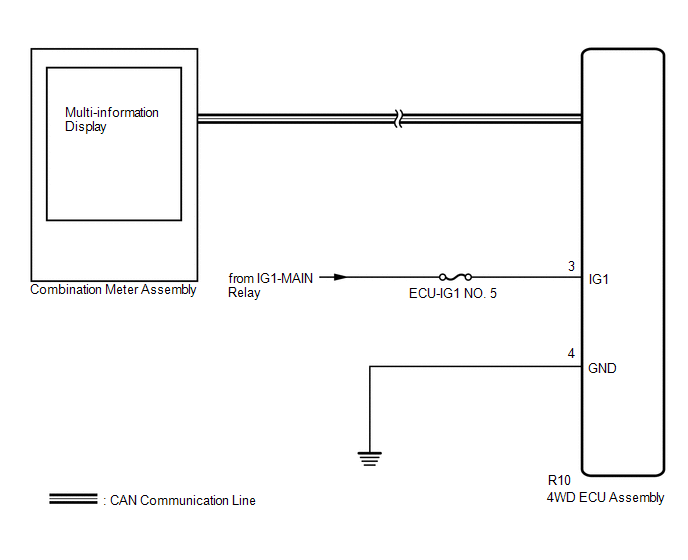
The 4WD ECU assembly is connected to the combination meter assembly via CAN communication.
If the 4WD ECU assembly stores any DTCs which are related to the dynamic torque control AWD system, the master warning light illuminates and the AWD warning message is displayed on the multi-information display in the combination meter assembly.
WIRING DIAGRAM
CAUTION / NOTICE / HINT
NOTICE:
- Inspect the fuses for circuits related to this system before performing the following inspection procedure.
-
When the 4WD ECU assembly is replaced with a known good one from another vehicle, it is necessary to perform calibration.
Click here
.gif)
HINT:
Check the condition of each related circuit connector before troubleshooting.
Click here
PROCEDURE
| 1. | CHECK FOR DTC (CAN COMMUNICATION SYSTEM AND DYNAMIC TORQUE CONTROL AWD SYSTEM) |
(a) Check if CAN communication system DTCs are output.
Click here
(b) Check if the dynamic torque control AWD system DTC is output.
Click here
| Result | Proceed to |
|---|---|
| CAN communication DTCs and dynamic control AWD system DTCs are not output | A |
| CAN communication DTCs are output | B |
| Dynamic torque control AWD system DTCs are output | C |
HINT:
If CAN communication DTCs are output, perform troubleshooting for the CAN communication system first.
| B | .gif) | GO TO CAN COMMUNICATION (HOW TO PROCEED WITH TROUBLESHOOTING) |
| C | | REPAIR CIRCUIT INDICATED BY OUTPUT CODE (DYNAMIC TORQUE CONTROL 4WD SYSTEM) |
|
.gif)
| 2. | CHECK 4WD ECU ASSEMBLY |
(a) Check if the 4WD ECU assembly connector is securely connected.
OK:
The connector is securely connected.
| NG | | CONNECT CONNECTOR TO ECU CORRECTLY |
|
| 3. | INSPECT BATTERY |
(a) Check the battery voltage.
Standard Voltage:
11 to 14 V
| NG | | CHECK CHARGING SYSTEM |
|
| 4. | CHECK HARNESS AND CONNECTOR (IG1 TERMINAL) |
(a) Disconnect the R10 4WD ECU assembly connector.
(b) Turn the engine switch on (IG).
(c) Measure the voltage according to the value(s) in the table below.
Standard Voltage:
| Tester Connection | Switch Condition | Specified Condition |
|---|---|---|
| R10-3 (IG1) - Body ground | Engine switch on (IG) | 11 to 14 V |
| NG | | REPAIR OR REPLACE HARNESS OR CONNECTOR |
|
| 5. | CHECK HARNESS AND CONNECTOR (GND TERMINAL) |
(a) Turn the engine switch off.
(b) Measure the resistance according to the value(s) in the table below.
Standard Resistance:
| Tester Connection | Condition | Specified Condition |
|---|---|---|
| R10-4 (GND) - Body ground | Always | Below 1 Ω |
| NG | | REPAIR OR REPLACE HARNESS OR CONNECTOR |
|
| 6. | READ VALUE USING TECHSTREAM (4WD WARNING LIGHT) |
(a) Connect the R10 4WD ECU assembly connector.
(b) Turn the engine switch off.
(c) Connect the Techstream to the DLC3.
(d) Turn the engine switch on (IG).
(e) Turn the Techstream on.
(f) Enter the following menus: Chassis / Four Wheel Drive / Data List.
(g) According to the display on the Techstream, read the Data List.
Chassis > Four Wheel Drive > Data List| Tester Display | Measurement Item | Range | Normal Condition | Diagnostic Note |
|---|---|---|---|---|
| 4WD Warning Light | AWD warning (multi-information display) | OFF or ON | OFF: Warning off ON: Warning on | - |
| Tester Display |
|---|
| 4WD Warning Light |
(h) Check the Techstream display condition of the 4WD Warning Light.
| Result | Proceed to |
|---|---|
| Display of the Data List remains OFF | A |
| Display of the Data List remains ON | B |
| A | | GO TO METER / GAUGE SYSTEM (HOW TO PROCEED WITH TROUBLESHOOTING) |
| B | | REPLACE 4WD ECU ASSEMBLY |
 Lost Communication with ECM / PCM "A" (U0100,U0126,U0129)
DESCRIPTION The 4WD ECU assembly receives signals from the ECM, skid control ECU (brake actuator assembly) and steering sensor via CAN communication. When DTCs indicating a CAN communication system ma ...
 AWD Warning Light does not Come ON
DESCRIPTION Refer to "AWD Warning Light Remains ON". Click here WIRING DIAGRAM Refer to "AWD Warning Light Remains ON". Click here CAUTION / NOTICE / HINT NOTICE: When the 4WD ECU assembly is repl ...
Other materials:
Lexus RX (RX 350L, RX450h) 2016-2025 Repair Manual > Can Communication System: Diagnosis System
DIAGNOSIS SYSTEM CHECK FOR INSTALLED SYSTEMS (ECUS AND SENSORS) THAT USE CAN COMMUNICATION (a) The systems (ECUs and sensors) that use CAN communication vary depending on the vehicle and optional equipment. Check which systems (ECUs and sensors) are installed to the vehicle. Bus ECU/Sensor Name ...
Lexus RX (RX 350L, RX450h) 2016-2025 Repair Manual > Navigation System: Visual Mute Signal Circuit between Radio Receiver and Multi-display
DESCRIPTION The radio receiver assembly sends a visual mute signal to the multi-display assembly. As a result, a black screen is displayed when the screen changes so that noise and distorted images are not displayed. When an open exists in the circuit, noise and distorted images will be displayed in ...
Lexus RX (RX 350L, RX450h) 2016-{YEAR} Owners Manual
- For your information
- Pictorial index
- For safety and security
- Instrument cluster
- Operation of each component
- Driving
- Lexus Display Audio system
- Interior features
- Maintenance and care
- When trouble arises
- Vehicle specifications
- For owners
Lexus RX (RX 350L, RX450h) 2016-{YEAR} Repair Manual

0.0138