Lexus RX (RX 350L, RX450h) 2016-2025 Repair Manual: Power Source Circuit
DESCRIPTION
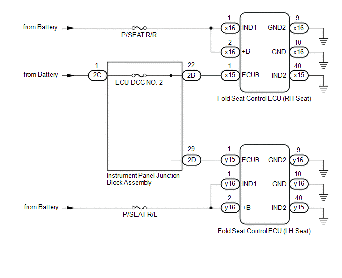
Power is supplied to each fold seat control ECU through fuses.
WIRING DIAGRAM
CAUTION / NOTICE / HINT
NOTICE:
Inspect the fuses for circuits related to this system before performing the following procedure.
PROCEDURE
| 1. | CHECK REAR POWER SEAT CONTROL SYSTEM (for Third Row) |
(a) Check that the rear power seat control system (for Third Row) function operates normally.
| Result | Proceed to |
|---|---|
| Fold/Return functions of both rear No .2 power seats do not operate normally. | A |
| Fold/Return functions of rear No. 2 power seat RH do not operate normally. | B |
| Fold/Return functions of rear No. 2 power seat LH do not operate normally. | C |
| B | .gif) | GO TO STEP 5 |
| C | | GO TO STEP 8 |
|
.gif)
| 2. | CHECK HARNESS AND CONNECTOR (BATTERY POWER SUPPLY) |
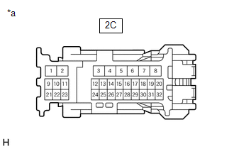
| (a) Disconnect the 2C instrument panel junction block assembly connector |
|
(b) Measure the voltage according to the value(s) in the table below.
Standard Voltage:
| Tester Connection | Condition | Specified Condition |
|---|---|---|
| 2C-1 - Body ground | Always | 11 to 14 V |
| NG | | REPAIR OR REPLACE HARNESS OR CONNECTOR |
|
| 3. | CHECK HARNESS AND CONNECTOR (BATTERY POWER SUPPLY) |
| (a) Disconnect the x15 fold seat control ECU (RH seat) connector. |
|
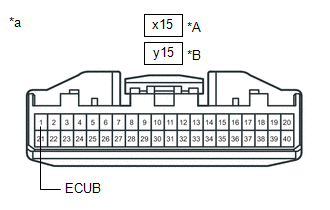
(b) Disconnect the y15 fold seat control ECU (LH seat) connector.
(c) Measure the voltage according to the value(s) in the table below.
Standard Voltage:
| Tester Connection | Condition | Specified Condition |
|---|---|---|
| x15-1 (ECUB) - Body ground | Always | 11 to 14 V |
| y15-1 (ECUB) - Body ground | Always | 11 to 14 V |
| OK | | PROCEED TO NEXT SUSPECTED AREA SHOWN IN PROBLEM SYMPTOMS TABLE |
|
| 4. | CHECK HARNESS AND CONNECTOR (INSTRUMENT PANEL JUNCTION BLOCK ASSEMBLY - FOLD SEAT CONTROL ECU (RH/LH SEAT)) |
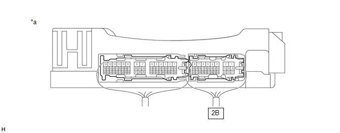
(a) Disconnect the 2B and 2D instrument panel junction block assembly connector
(b) Measure the resistance according to the value(s) in the table below.
Standard Resistance:
| Tester Connection | Condition | Specified Condition |
|---|---|---|
| 2B-22 or x15-1 (ECUB) - Body ground | Always | 10 kΩ or higher |
| 2D-29 or y15-1 (ECUB) - Body ground | Always | 10 kΩ or higher |
| OK | | REPLACE INSTRUMENT PANEL JUNCTION BLOCK ASSEMBLY |
.gif)
| NG | | REPAIR OR REPLACE HARNESS OR CONNECTOR |
| 5. | INSPECT INSTRUMENT PANEL JUNCTION BLOCK ASSEMBLY |
(a) Measure the voltage according to the value(s) in the table below.
| *a | Component with harness connected (Instrument Panel Junction Block Assembly) | - | - |
Standard Voltage:
| Tester Connection | Condition | Specified Condition |
|---|---|---|
| 2B-22 - Body ground | Always | 11 to 14 V |
| NG | | REPLACE INSTRUMENT PANEL JUNCTION BLOCK ASSEMBLY |
|
| 6. | CHECK HARNESS AND CONNECTOR (INSTRUMENT PANEL JUNCTION BLOCK ASSEMBLY - FOLD SEAT CONTROL ECU (RH SEAT)) |
(a) Disconnect the x15 fold seat control ECU (RH seat) connector.
(b) Measure the resistance according to the value(s) in the table below.
Standard Resistance:
| Tester Connection | Condition | Specified Condition |
|---|---|---|
| 2B-22 - x15-1 (ECUB) | Always | Below 1 Ω |
| NG | | REPAIR OR REPLACE HARNESS OR CONNECTOR |
|
| 7. | CHECK HARNESS AND CONNECTOR (FOLD SEAT CONTROL ECU (RH SEAT) - BATTERY POWER SUPPLY AND BODY GROUND) |
| (a) Disconnect the x16 fold seat control ECU (RH seat) connector. |
|
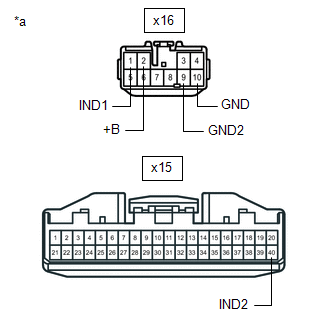
(b) Measure the voltage and resistance according to the value(s) in the table below.
Standard Voltage:
| Tester Connection | Condition | Specified Condition |
|---|---|---|
| x16-1 (IND1) - Body ground | Always | 11 to 14 V |
| x16-2 (+B) - Body ground | Always | 11 to 14 V |
(c) Measure the resistance according to the value(s) in the table below.
Standard Resistance:
| Tester Connection | Condition | Specified Condition |
|---|---|---|
| x15-40 (IND2) - Body ground | Always | Below 1 Ω |
| x16-9 (GND2) - Body ground | Always | Below 1 Ω |
| x16-10 (GND) - Body ground | Always | Below 1 Ω |
| OK | | PROCEED TO NEXT SUSPECTED AREA SHOWN IN PROBLEM SYMPTOMS TABLE |
| NG | | REPAIR OR REPLACE HARNESS OR CONNECTOR |
| 8. | INSPECT INSTRUMENT PANEL JUNCTION BLOCK ASSEMBLY |
(a) Measure the voltage according to the value(s) in the table below
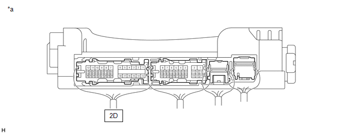
| *a | Component with harness connected (Instrument Panel Junction Block Assembly) | - | - |
Standard Voltage:
| Tester Connection | Condition | Specified Condition |
|---|---|---|
| 2D-29 - Body ground | Always | 11 to 14 V |
| NG | | REPLACE INSTRUMENT PANEL JUNCTION BLOCK ASSEMBLY |
|
| 9. | CHECK HARNESS AND CONNECTOR (INSTRUMENT PANEL JUNCTION BLOCK ASSEMBLY - FOLD SEAT CONTROL ECU (LH SEAT)) |
(a) Disconnect the y15 fold seat control ECU (LH seat) connector.
(b) Measure the resistance according to the value(s) in the table below.
Standard Resistance:
| Tester Connection | Condition | Specified Condition |
|---|---|---|
| y15-1 (ECUB) - 2D-29 | Always | Below 1 Ω |
| NG | | REPAIR OR REPLACE HARNESS OR CONNECTOR |
|
| 10. | CHECK HARNESS AND CONNECTOR (FOLD SEAT CONTROL ECU (LH SEAT) - BATTERY POWER SUPPLY AND BODY GROUND) |
| (a) Disconnect the y16 fold seat control ECU (LH seat) connector. |
|

(b) Measure the voltage according to the value(s) in the table below.
Standard Voltage:
| Tester Connection | Condition | Specified Condition |
|---|---|---|
| y16-1 (IND1) - Body ground | Always | 11 to 14 V |
| y16-2 (+B) - Body ground | Always | 11 to 14 V |
(c) Measure the resistance according to the value(s) in the table below.
Standard Resistance:
| Tester Connection | Condition | Specified Condition |
|---|---|---|
| y15-40 (IND2) - Body ground | Always | Below 1 Ω |
| y16-9 (GND2) - Body ground | Always | Below 1 Ω |
| y16-10 (GND) - Body ground | Always | Below 1 Ω |
| OK | | PROCEED TO NEXT SUSPECTED AREA SHOWN IN PROBLEM SYMPTOMS TABLE |
| NG | | REPAIR OR REPLACE HARNESS OR CONNECTOR |
 Power Seat Motor Circuit
DESCRIPTION When a switch of the fold seat switch assembly or No. 1 fold seat switch assembly is pushed, the fold seat control ECU receives a switch operation signal and operates each motor. WIRING DI ...

Other materials:
Lexus RX (RX 350L, RX450h) 2016-2025 Repair Manual > Safety Connect System: Dcm Operation History
DCM OPERATION HISTORY DCM OPERATION HISTORY HINT:
This function shows the telematics network status when the DCM (telematics transceiver) was operated. Use this when no DTC is present but this telematics system was unable to connect to the call center. This symptom may occur if cell phone signal ...
Lexus RX (RX 350L, RX450h) 2016-2025 Repair Manual > Power Steering System: Torque Sensor Zero Point Adjustment Undone (C1515)
DESCRIPTION This DTC does not indicate a malfunction. The power steering ECU assembly stores this DTC when it determines that torque sensor zero point calibration has not been performed. DTC No. Detection Item DTC Detection Condition Trouble Area Warning Indicate Return-to-normal Condit ...
Lexus RX (RX 350L, RX450h) 2016-{YEAR} Owners Manual
- For your information
- Pictorial index
- For safety and security
- Instrument cluster
- Operation of each component
- Driving
- Lexus Display Audio system
- Interior features
- Maintenance and care
- When trouble arises
- Vehicle specifications
- For owners
Lexus RX (RX 350L, RX450h) 2016-{YEAR} Repair Manual

0.0127